mike 109444
Member
- Messages
- 4,878
You have now found why you need to lift one leg (of resistor !) to meter it's value.Hi Mike, sorry for causing you all this bother and didn't want it to take up your time and I really appreciate it. My brain's frazzled after all this so if what I say doesn't make sense it's my lack of understanding.
Wasn't sure where I should have connected the red & black probes of my meter but when I checked across the feed from the chip (the one with the diode on) to each of the thyristor legs in turn I got 9v, @ Cathode, 9v @ Anode and ALREADY had 6v @ Gate without pressing the trigger ( pressing the trigger seem to make no difference ) was same for all 3. Would this explain why I get an arc by touching the wire to the earth clamp when the trigger isn't pressed?
Anyhow, as mentioned earlier I checked out the resistor values and compared them to actual readings including their 5 or 10% allowance and I know you said that a more reliable reading would be obtained by desoldering at least 1 leg but as a guide, 97% of them ( just resistors checked ) were remarkably accurate.
The following anomalies may or may not explain something but it's a bit over my head and thought you might know better.
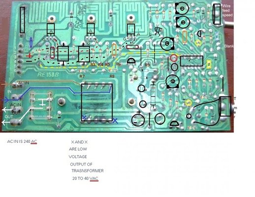
1) The resistor ( on the RIGHT of the Orange capacitor as we look at it from underneath almost opposite the Rightmost thyristor ) which connects to the track that goes to the Gate is rated at 47 ohms and is verified on the board and the colour code, the actual reading was 58 ohms. ( and beeps at the same time )
2) The resistor 2nd LEFT of the same orange transistor also connects to the same track that goes to the same gate, is rated 100 ohms, again verified on the card and colour code but the actual reading is 61.8 ohms.
3) The next resistor left ( 3rd left of the same orange capacitor ) goes to the track connected to the gate of the middle thyristor is rated 330 ohms verified on board and colour coded and actual reading was 203 ohms.
Hope this helps.
You meter ideally would have the black probe connected to 0 Volt rail, finding this may not be easy on this pcb. If you get the number off the chip (one with diode across it) then it should be possible to look it up and find which of it's pins is the 0 volt supply pin and from that find the 0 volt track to attach meter black probe to. Once you have connected to that then you can use the red probe to poke around the thyristor and note the voltage readings.
Ref the "beeping" from meter I would assume that was as a result of a capacitor charging from your meter giving a short to your meter.
Might be worth lifting one side of each of the two large diodes that connect to the neg side of the feed to the motor and metering with meter on diode test.