Dear All,
I have a Arc Welder with 250 Amps output that can work on both single phase and two phase 7.5 KVA ( 230V / 440 V , 50 Hz ) with 250 Amps AC Output and Open Ckt voltage of about 80 Volts.
I was checking the Possibility of upgrading my old welder that use a tapped choke connected to the secondary with 5 different taps to select 5 different output AC welding current. This required manual change of holder cable from one selection output stud to the other. This is very difficult and could not select the correct power required for welding as only 5 output studs are there and the time taken is more for changing from one output stud to the other.
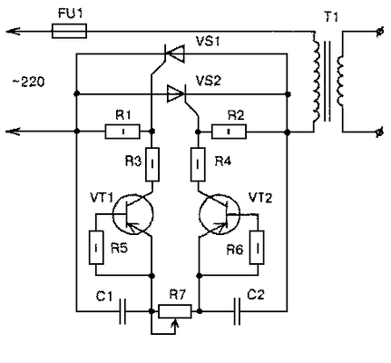
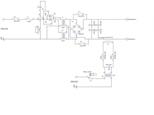
I have seen many schematic on web using either a welding transformer that has a movable core to select the current or using a control circuit in the primary side of the transformer. But to control from the primary side of the transformer in my welder would be difficult as I need to use it on both single phase and two phase power.
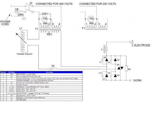
So thought of using a variable inductor in the Secondary of the welding transformer to control the welding current .Need your help to check this circuit attached and let me know if you see any problem or if I need any change in this design .
If there are any other schematics that you have seen to control the secondary with out the variable inductor would be good.
I would also like to know how we need to calculate the number of turns and the size of the variable inductor coil to be used for controlling 250 Amps welding current.
Thanks ,
Regards,
John


