


You are using an out of date browser. It may not display this or other websites correctly.
You should upgrade or use an alternative browser.
You should upgrade or use an alternative browser.
No Gas welder
- Thread starter rotivator
- Start date
mike 109444
Member
- Messages
- 4,671
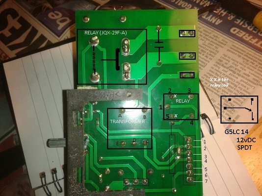
Set your meter to DC volts, put one meter probe on the pin 1 of RELAY and other meter probe on its pin 4. Make a note of any reading before pulling trigger. Then pull trigger and note any reading. Now keeping the probe on pin 1 move other probe to its pin 3. Note any reading before pulling trigger then note any reading when trigger pulled.
Make a list thus
1 to 4 no trigger = ........
1 to 4 triggered = .........
1 to 3 no trigger = ........
1 to 3 triggered = .........
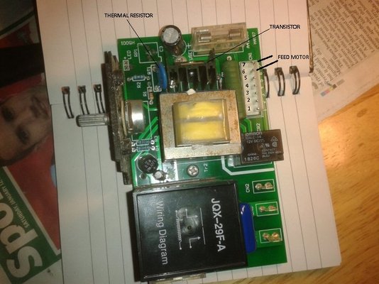
Can you also make a note of any markings on the transistor that is mounted to the black heatsink.
Make a list thus
1 to 4 no trigger = ........
1 to 4 triggered = .........
1 to 3 no trigger = ........
1 to 3 triggered = .........
Can you also make a note of any markings on the transistor that is mounted to the black heatsink.
mike 109444
Member
- Messages
- 4,671
looks like the transistor has gone duff. < £5.00
http://www.ebay.co.uk/sch/i.html?_f....TRC0.A0.H0.Xtip35c.TRS0&_nkw=tip35c&_sacat=0
Was the wire on the spool secured (fixed) at it's end ? Just wondering if that caused the motor to stall and pop the transistor.
http://www.ebay.co.uk/sch/i.html?_f....TRC0.A0.H0.Xtip35c.TRS0&_nkw=tip35c&_sacat=0
Was the wire on the spool secured (fixed) at it's end ? Just wondering if that caused the motor to stall and pop the transistor.
mike 109444
Member
- Messages
- 4,671
If not ebay then RS (if you have one near you. I would have recommended Maplins but they are pants now and don't list a TIP35C, they have others that MIGHT do but just as well to get correct one.
It is quite a common device so should be no problem getting one.
Let us know the outcome.
It is quite a common device so should be no problem getting one.
Let us know the outcome.
mike 109444
Member
- Messages
- 4,671
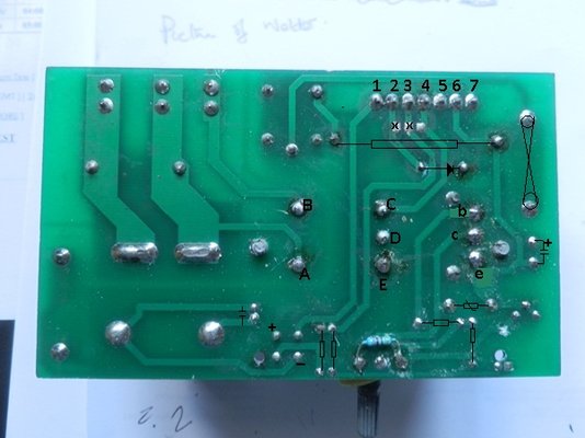
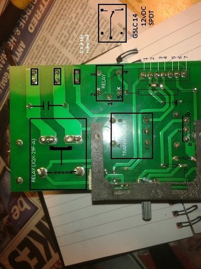
Can you post a clear pic of both sides of the pcb (with the black plastic frame removed) as it is difficult to follow the circuit with the limited pics I have.
mike 109444
Member
- Messages
- 4,671
Sad they have gone that way but even the small electronics shops are gone to.
mike 109444
Member
- Messages
- 4,671
Might be a silly question but have you checked the on board fuse ?
Where does the bottom connection to the fuse go/come from 9the end nearest the capacitor as it is not clear on the pics. I can see one end goes to the relay pin 4.
The soldering on D2 looks like it could do with being redone (between the black heatsink and the big green resistor).
I am drawing out the diagram to try and work it out.
mike 109444
Member
- Messages
- 4,671
Having looked at both your pcb pic and the other one I noticed there is a blob of solder on one but not the other
Have you removed a blob of solder that joined the two point at "x x" (linking the tracks for pin 2 and 3) If yes then re-blob. If no then don't.
If no then desolder one leg of D1 and lift it up. Set your meter to Diode test ( will have an arrow with a line across the point ) then meter across the diode D1 one probe on the pin still left on pcb and one on the "free" pin. Note the reading. Now swap around the meter leads and meter again (so if the meter black lead was on the pcb pin it now be on the "free" pin). Note the reading.
On a good diode you should see something like 0.400 to 0.600 ish with meter one way round and maybe 1._ _ with meter other way. If you see 0.00 or the 1._ _ both ways then the diode is duff.
rotivator
New Member
- Messages
- 26
- Location
- Cornwall UK
Hi Mike Thanks for all your help with my welder. I must say that the level of help you have given me has been exemplary. Its not often that anyone will put themselves out like you have.
Now back to the welder.. When it first stopped working the wire had run out. When I replaced the wire the machine didn't work. I checked the fuse then the internal fuses. I must have run my fingers over the panel to see if any breaks and I think I did rub a blob of solder off. Anyway I then found that the trigger wire spade had come off. After that you know the story. I was thinking about that solder joint but didn't want to join it in case it ruined the panel.
I bought this machine a few years ago and its had very little use. I found that while I was playing around with the inside the wiring kept falling apart so its been an experience ! ( I am not technical) Once again thanks for all your help. The blob of soled cured it and I now know a lot more about the workings
Dave
mike 109444
Member
- Messages
- 4,671
Thank you very much Dave for posting back the result. I do enjoy the challenge of remote diagnoses of faults 9have a few colleges that I have to help from time to time  ) but have been stuck on a site late at night an having help/support at the end of the phone is a blessing.
Glad you have increased your knowledge of what goes on inside the machine!
Bit disconcerting that these machines seam so poorly put together as they seam to have much the same level of components as many other "hobby" type machines.
I will try and post up the part of the circuit I did draw/work out for future ref should anybody come across this post.
) but have been stuck on a site late at night an having help/support at the end of the phone is a blessing.Glad you have increased your knowledge of what goes on inside the machine!
Bit disconcerting that these machines seam so poorly put together as they seam to have much the same level of components as many other "hobby" type machines.
I will try and post up the part of the circuit I did draw/work out for future ref should anybody come across this post.
