


This is my first post to this forum and having booked myself on a night time school course to learn MIG and ARC welding, I obviously needed a welding machine to pursue my newly learnt skills.
Thus I could have gone and bought a new shinny hobby Mig welder but restoring and converting one provided me with the following benefits of which I thought I would share with everyone.
1. A deeper understanding of how a MIG welder works.
2. Euro torch conversion, which allows me to use a 3 meter torch lead as the standard built in torches in most hobby welders are far to short.
3. Upgrading the factory fitted cables to minimize volt drops.
4. The process of restoring something brings immense satisfaction, and in the case of my project, to make the thing perform much better than a new boxed one, that has a longer torch to suit my requirements.
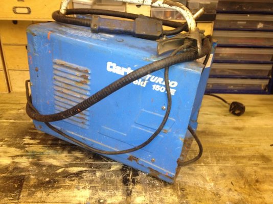
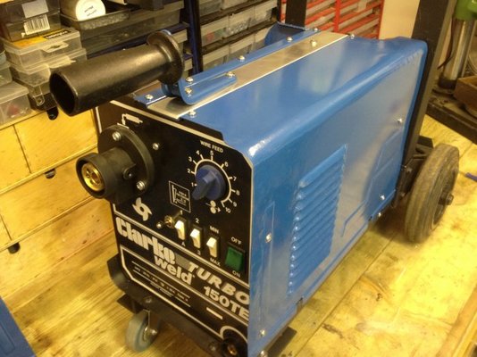
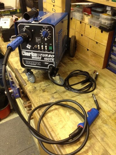
The patient - and ebay purchased Clarke 150TE Mig Welder that was described as working but needing some attention. With next day delivery it landed at my doorstep at just under £47, what a bargain.
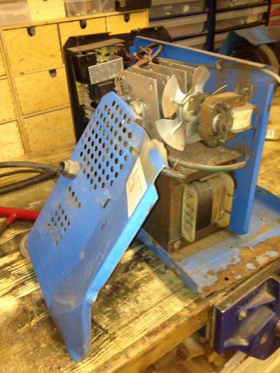
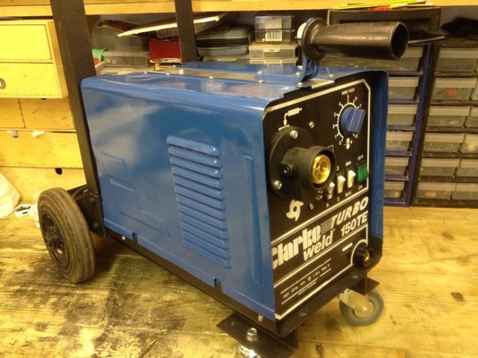
Below are pictures of the BEFORE , DURING and AFTER the restoration
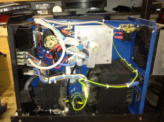
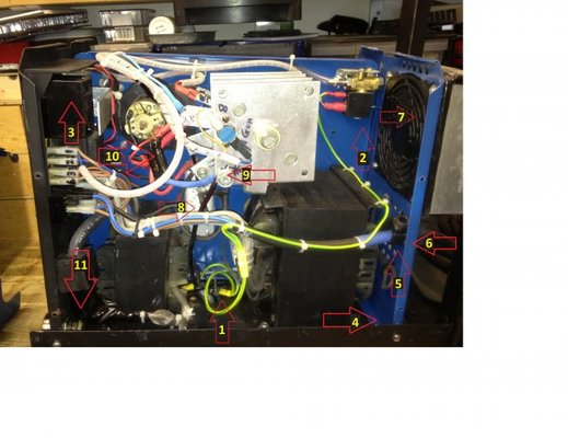
A summary of the main points of the Clarke restoration (see below photo with red arrows / labels that correlate to the numbers 1-11.
1 - The original chassis had a tiny earth lead that was just was not going to pass my standards, so the transformer and choke were individually bonded to a central earth point and electrical grease applied to the metal chassis, bolts and the soldered and crimped wire lugs to prevent future oxidation. Transformer and choke were no longer riveted but instead a nut , bolt and washer job.
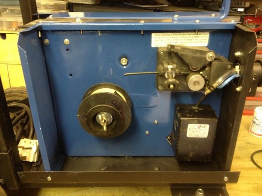
2. Along with the Euro conversion, the welder obviously required a gas solenoid, it was installed with a custom made stainless bracket and the wires wrapped in silicone sleeving.
3. The original circuit board was working but needed some attention, so out came the soldering iron where all electrolytic capacitors, power transistors and the IC were replaced. Also replaced was the potentiometer. The value was 100 K linear pot ( not the logarithmic type). Current damaged or weakened tracks were repaired and board de-fluxed. The relay cases was carefully opened and the electrical contacts serviced.
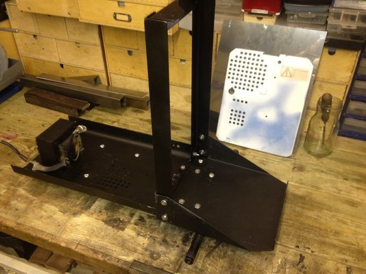
4. The original chassis base was powder coated Clarke blue, this was de-rusted and repainted with black Hammerite stone chip.
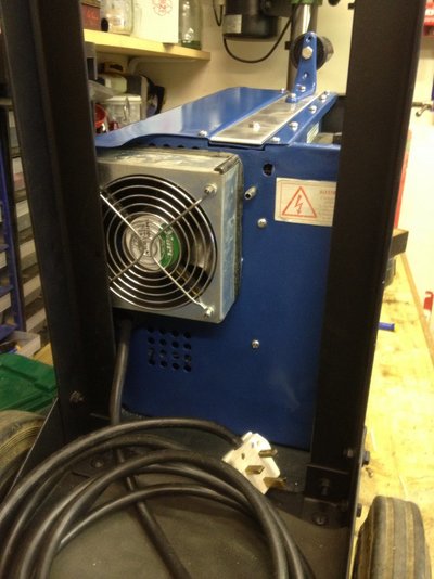
5. The existing mains cable feeding the welder was unsafe and in my opinion an inadequate gauge , so to prevent any volt drops, increase the cable length, and install a more durable cord, namely a 2.5 mm per core heavy duty rubber cable was used. I had 3 meters left over from another project.
6. The side panels and casings/lids were panel beated back into shape, de-rusted, primed and painted with the closest blue spray paint I could buy locally (Halfords). It was Ford Orion Blue, followed by a few coats of clear lacquer.
7. The original cooling fan was working fine but was just not good enough, so installed was a 1.2 amp DC fan with cover guards on both sides (why a guard on inside i hear you say, well i had it on the bench, that's why) A fan drawing 1.2 amps (fitted to a fused power supply on the wire spool side of the chassis) is really powerful and thus needless to say, the air flow though the welder is significant.
8. A 4700 uF 63V low ESR electrolytic capacitor was installed to a custom bracket, with the positive and negative bolt terminals triple insulated with clear heat shrink tubing. I did not want to jeopardize the welders minimum current setting by going to high a value , thus the 4700 uF capacitor still allows welding of thin gauge steel.
9. All new bolts and washers fitted to the rectifier with electrical grease to minimize oxidation between the different metal types. Good clean electrical connections is the objective here and throughout the rest of the wiring.
10. A drain resistor fitted across the capacitor as per number 8 above, 800 ohm 10 watt, with heat shrinked silicone wire.
11. A Dinse connector was fitted to the choke output, the original Clarke front panel cut out for the cable gland fitted the new Dinse connector pefectly as it already had the key slote. A new 25 mm² earth lead and a heavy duty Parweld earth clamp fitted.
Additional changes:
The Motor leads originally relied on loose fitting push on spade terminals, thus making for terrible electrical connections, thus new wires were soldered and a Deans connector was used between the motor and the control board. The motor was serviced and the old grease in the motor feed unit removed and replaced.
On the topic of the motor, a change over switch was fitted to the front panel next to the existing power switches, thus allowing for the motor to be turned off but allowing gas to still flow when the torch gun trigger is pulled. This allows for a gas flow gauge to be used with no wire being feed through. Although its simple enough to undo the wire feed tensioner, I incorporated the switch idea early in the re-build process, so it was no big deal.
Castor wheels and a Gas bottle tray was built with angle iron installed underneath the welder chassis plate to stiffen it up so as to avoid wrapping and twisting with the weight of the transformers.
Thus I could have gone and bought a new shinny hobby Mig welder but restoring and converting one provided me with the following benefits of which I thought I would share with everyone.
1. A deeper understanding of how a MIG welder works.
2. Euro torch conversion, which allows me to use a 3 meter torch lead as the standard built in torches in most hobby welders are far to short.
3. Upgrading the factory fitted cables to minimize volt drops.
4. The process of restoring something brings immense satisfaction, and in the case of my project, to make the thing perform much better than a new boxed one, that has a longer torch to suit my requirements.
The patient - and ebay purchased Clarke 150TE Mig Welder that was described as working but needing some attention. With next day delivery it landed at my doorstep at just under £47, what a bargain.
Below are pictures of the BEFORE , DURING and AFTER the restoration
A summary of the main points of the Clarke restoration (see below photo with red arrows / labels that correlate to the numbers 1-11.
1 - The original chassis had a tiny earth lead that was just was not going to pass my standards, so the transformer and choke were individually bonded to a central earth point and electrical grease applied to the metal chassis, bolts and the soldered and crimped wire lugs to prevent future oxidation. Transformer and choke were no longer riveted but instead a nut , bolt and washer job.
2. Along with the Euro conversion, the welder obviously required a gas solenoid, it was installed with a custom made stainless bracket and the wires wrapped in silicone sleeving.
3. The original circuit board was working but needed some attention, so out came the soldering iron where all electrolytic capacitors, power transistors and the IC were replaced. Also replaced was the potentiometer. The value was 100 K linear pot ( not the logarithmic type). Current damaged or weakened tracks were repaired and board de-fluxed. The relay cases was carefully opened and the electrical contacts serviced.
4. The original chassis base was powder coated Clarke blue, this was de-rusted and repainted with black Hammerite stone chip.
5. The existing mains cable feeding the welder was unsafe and in my opinion an inadequate gauge , so to prevent any volt drops, increase the cable length, and install a more durable cord, namely a 2.5 mm per core heavy duty rubber cable was used. I had 3 meters left over from another project.
6. The side panels and casings/lids were panel beated back into shape, de-rusted, primed and painted with the closest blue spray paint I could buy locally (Halfords). It was Ford Orion Blue, followed by a few coats of clear lacquer.
7. The original cooling fan was working fine but was just not good enough, so installed was a 1.2 amp DC fan with cover guards on both sides (why a guard on inside i hear you say, well i had it on the bench, that's why) A fan drawing 1.2 amps (fitted to a fused power supply on the wire spool side of the chassis) is really powerful and thus needless to say, the air flow though the welder is significant.
8. A 4700 uF 63V low ESR electrolytic capacitor was installed to a custom bracket, with the positive and negative bolt terminals triple insulated with clear heat shrink tubing. I did not want to jeopardize the welders minimum current setting by going to high a value , thus the 4700 uF capacitor still allows welding of thin gauge steel.
9. All new bolts and washers fitted to the rectifier with electrical grease to minimize oxidation between the different metal types. Good clean electrical connections is the objective here and throughout the rest of the wiring.
10. A drain resistor fitted across the capacitor as per number 8 above, 800 ohm 10 watt, with heat shrinked silicone wire.
11. A Dinse connector was fitted to the choke output, the original Clarke front panel cut out for the cable gland fitted the new Dinse connector pefectly as it already had the key slote. A new 25 mm² earth lead and a heavy duty Parweld earth clamp fitted.
Additional changes:
The Motor leads originally relied on loose fitting push on spade terminals, thus making for terrible electrical connections, thus new wires were soldered and a Deans connector was used between the motor and the control board. The motor was serviced and the old grease in the motor feed unit removed and replaced.
On the topic of the motor, a change over switch was fitted to the front panel next to the existing power switches, thus allowing for the motor to be turned off but allowing gas to still flow when the torch gun trigger is pulled. This allows for a gas flow gauge to be used with no wire being feed through. Although its simple enough to undo the wire feed tensioner, I incorporated the switch idea early in the re-build process, so it was no big deal.
Castor wheels and a Gas bottle tray was built with angle iron installed underneath the welder chassis plate to stiffen it up so as to avoid wrapping and twisting with the weight of the transformers.
-
 IMG_4256.jpg83.3 KB · Views: 796
 -
 IMG_4257.jpg127.3 KB · Views: 741
 -
 IMG_4287.jpg62.8 KB · Views: 760
 -
 IMG_4304.jpg73.8 KB · Views: 757
 -
 IMG_4339.jpg65 KB · Views: 790
 -
 IMG_4926.jpg87.5 KB · Views: 820
 -
 IMG_4941.jpg82.5 KB · Views: 808
 -
 IMG_4944.jpg70 KB · Views: 770
 -
 IMG_4947.jpg106.1 KB · Views: 775
 -
 IMG_4948.jpg86.1 KB · Views: 783
 -
 IMG_4956.jpg147.2 KB · Views: 847
 -
 Labled.jpg71.3 KB · Views: 846
Last edited:
 first time I've seen an earth wire on a gas solenoid coil
")


