


Hello Folks, I bought a Cebora pocket 25 Plasma cutter at an autojumble last year, the seller telling me it was in good working order, however when I got it home to try it out, it turns out that it didn't work.
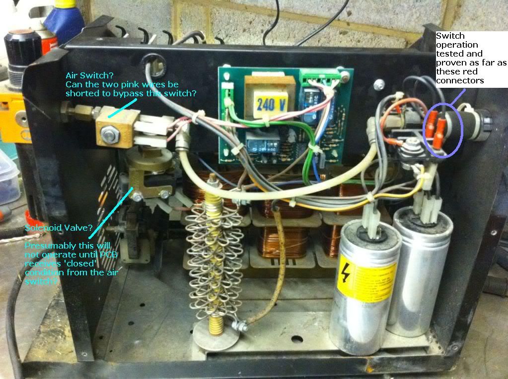
I've opened the case and on the plus side, nothing is burnt or appears damaged. When you switch it on, the fan kicks in and the power switch lights up, which is always a good sign!
When the button is pressed (and the nozzle pressed into the workpiece as this doesn't have an HF start) nothing happens. No arc, no flow of compressed air, not even a click of a relay.
I've done a bit of fault finding on the torch and have proven that the thumb switch and the nozzle switch both open and close as they should, checking continuity and insulation right back to the PCB.
I managed to get a basic electrical diagram from SCREWDRIVER'S POST, he has the same cutter and had a similar issue. However, what I'm not sure of is what each component on the diagram is, I can work out some of the obvious ones but not all of them.
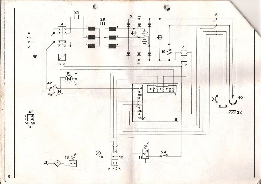
The contactors are all open, if i close the one towards the rear, the transformer starts humming ; not sure what to make from that.
So, I noted that if the air pressure switch had failed, this might prevent the cutter from doing anything else even when buttons pressed. Would this be right?
If so, can I short it as below (also can anyone confirm that i've correctly identified the air pressure switch and the solenoid valve)
Finally, does anybody have a cct diagram for the PCB?
I've opened the case and on the plus side, nothing is burnt or appears damaged. When you switch it on, the fan kicks in and the power switch lights up, which is always a good sign!
When the button is pressed (and the nozzle pressed into the workpiece as this doesn't have an HF start) nothing happens. No arc, no flow of compressed air, not even a click of a relay.
I've done a bit of fault finding on the torch and have proven that the thumb switch and the nozzle switch both open and close as they should, checking continuity and insulation right back to the PCB.
I managed to get a basic electrical diagram from SCREWDRIVER'S POST, he has the same cutter and had a similar issue. However, what I'm not sure of is what each component on the diagram is, I can work out some of the obvious ones but not all of them.
The contactors are all open, if i close the one towards the rear, the transformer starts humming ; not sure what to make from that.
So, I noted that if the air pressure switch had failed, this might prevent the cutter from doing anything else even when buttons pressed. Would this be right?
If so, can I short it as below (also can anyone confirm that i've correctly identified the air pressure switch and the solenoid valve)
Finally, does anybody have a cct diagram for the PCB?


 I would expect something like 24 or 42Volt AC in welding plant.


