Dr.Al
Forum Supporter
- Messages
- 2,816
- Location
- Gloucestershire, UK
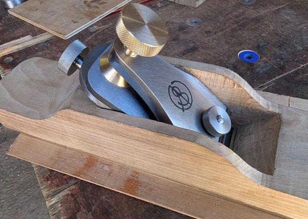
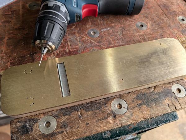
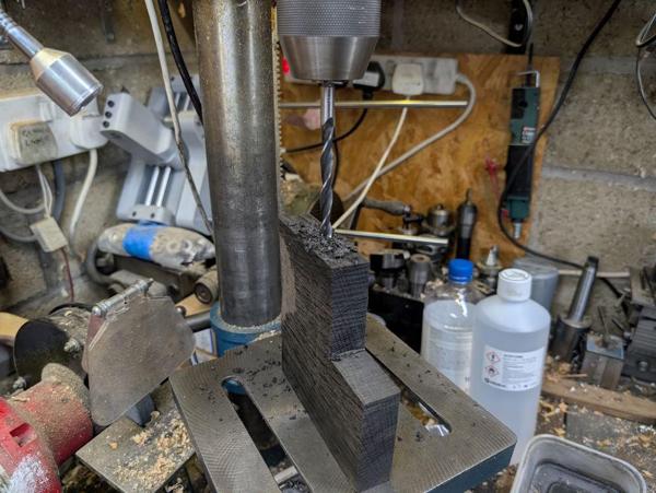
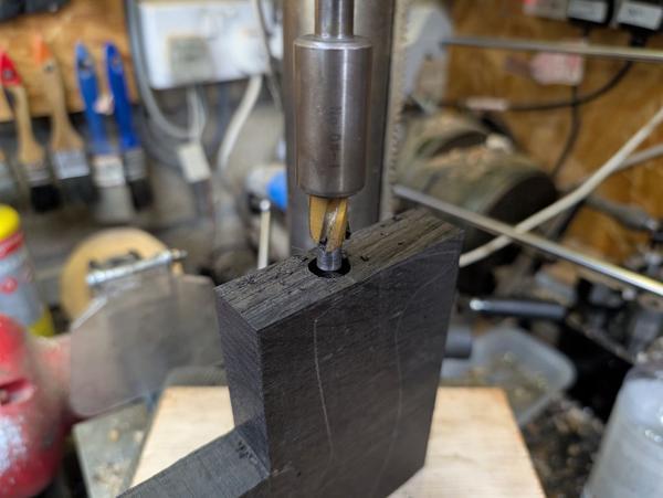
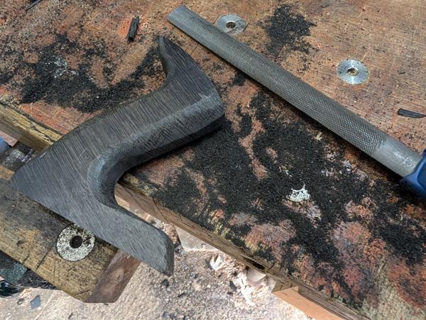
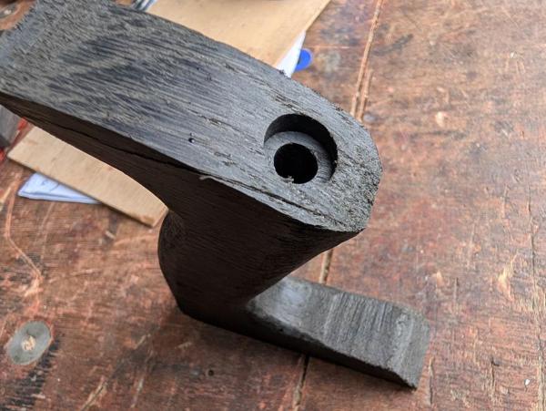
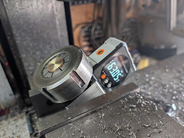
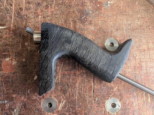
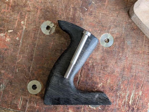
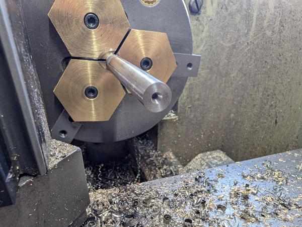
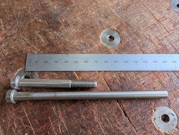
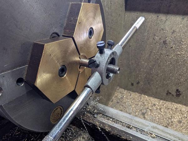
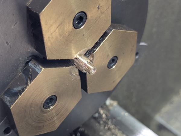
This morning I've been making the hardware to go with the lever cap, but first I decided I wanted a larger thread for the clamping screw. I put an M8 screw in the mill's collet chuck and screwed the lever cap onto it and that allowed me to put it in the vice in such a way that the hole was aligned with the spindle:
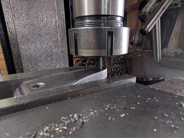
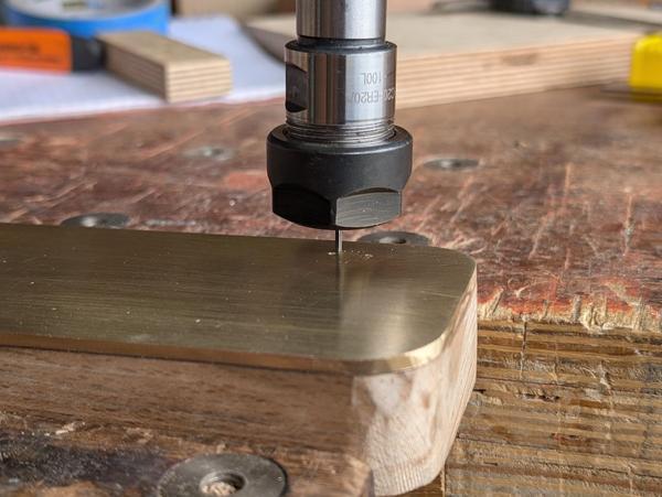
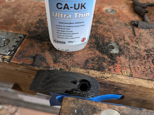
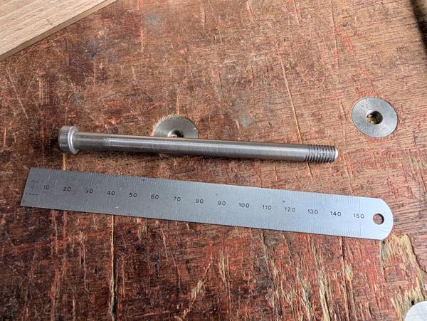
After drilling it out 8.8 mm, I took it over to the bench vice and tapped M10 × 1.25.
I probably would have gone with M12 × 1.25 if I had the tap, but my collection "only" included M12 × 1, M12 × 1.5 and M12 × 1.75! I'm sure either of the finer pitch ones would have been okay, but the 1.25 mm pitch just seemed about right for this application.
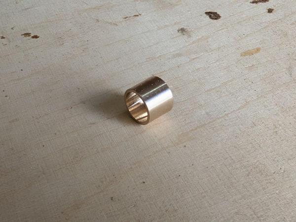
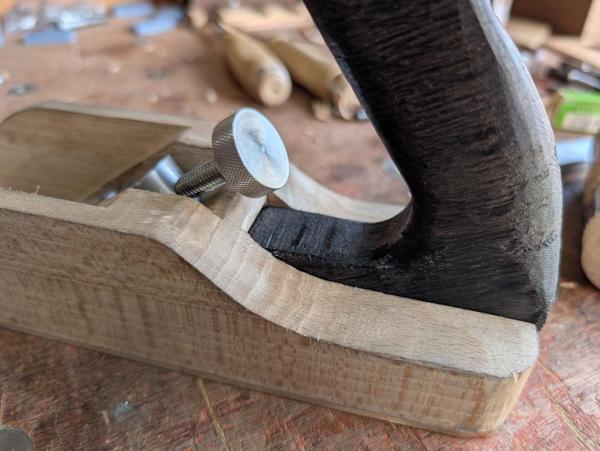
Next up was a very simple knurled nut for the pivot screw:
That can be quite small as it is never properly tightened, just snugged lightly up against the lever cap before tightening the clamping screw.
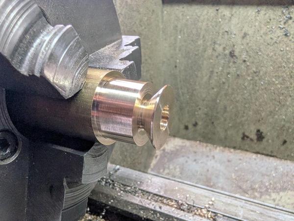
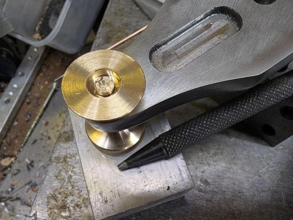
I wanted a clamping arrangement a bit like the one on my Veritas low-angle smoothing plane. That has a large foot that presses down on the blade (there's no cap iron on the Veritas), spreading the force. I started by making the foot out of a bit of 32 mm brass, turning it down to 26 mm and then putting a 45° taper on it. It got drilled through 6 mm and counterbored 12 mm:
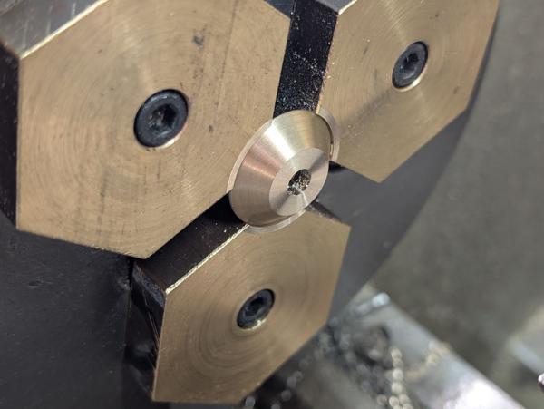
After parting off, it went in the home-made soft jaws for facing to length:
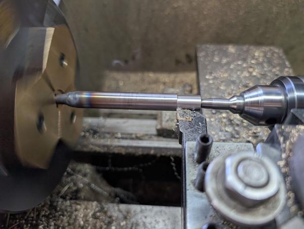
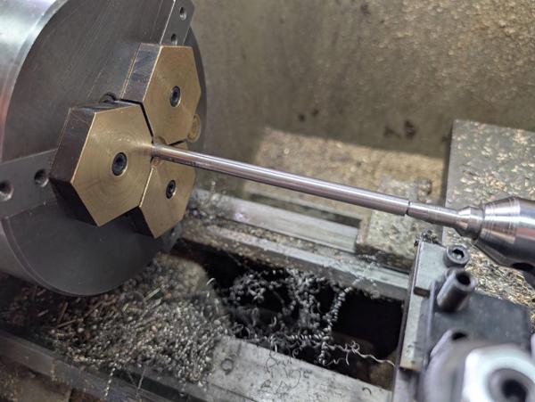
The clamping screw itself was made out of the same bar of brass. I used a tool with a big radius on it to reduce the diameter:
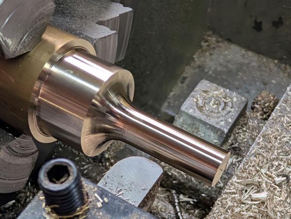
It didn't need a radius like that, I just did it because I felt like it.
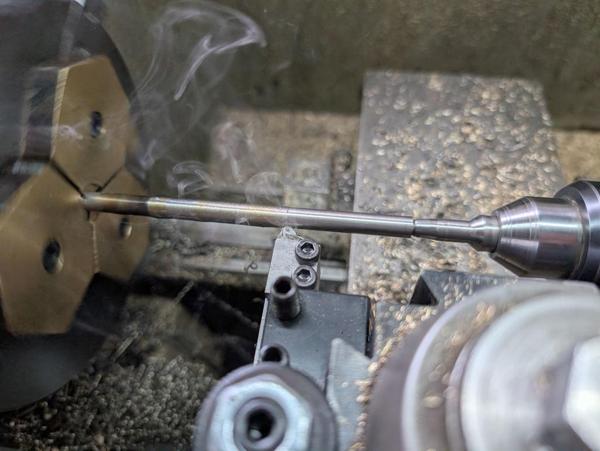
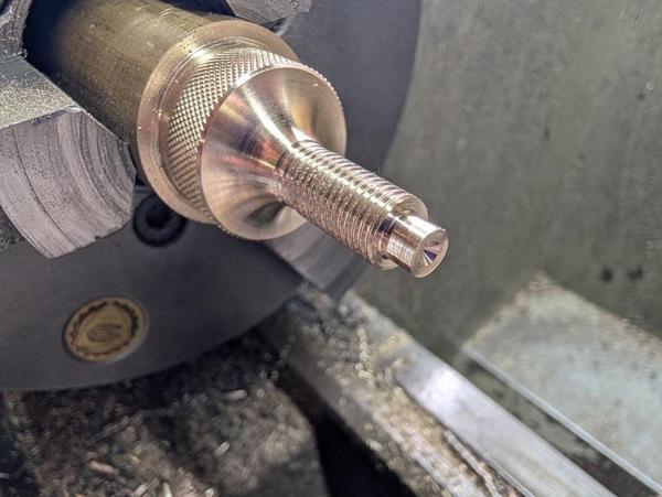
The bigger section got knurled, the smaller section threaded M10 × 1.25 and the tip reduced and lightly spot drilled:
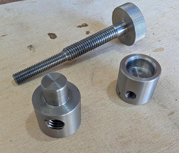
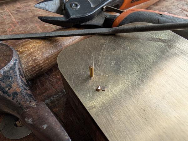
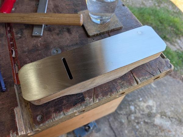
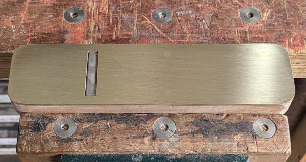
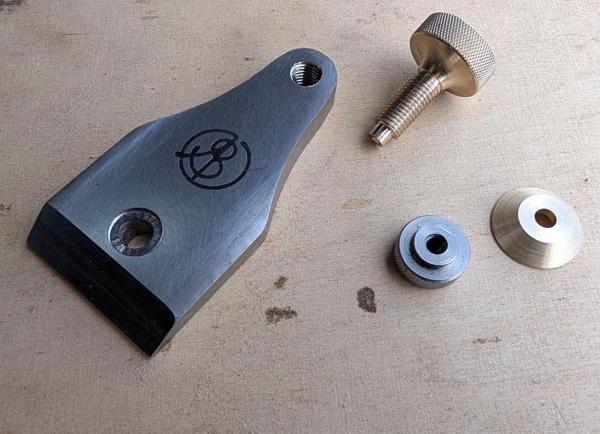
All of the above gave me this kit of parts:
On the Veritas lever cap, the foot is held in place with a circlip:
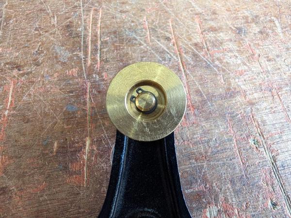
That is a very sensible option for a mass-produced part, but I'm only making one and I didn't have any circlips small enough. Instead, I assembled it all and used a punch to mangle the brass tip a bit so it couldn't go back through the hole:
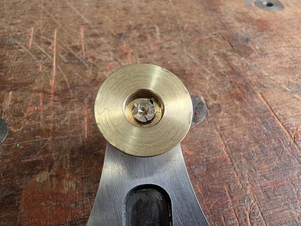
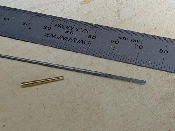
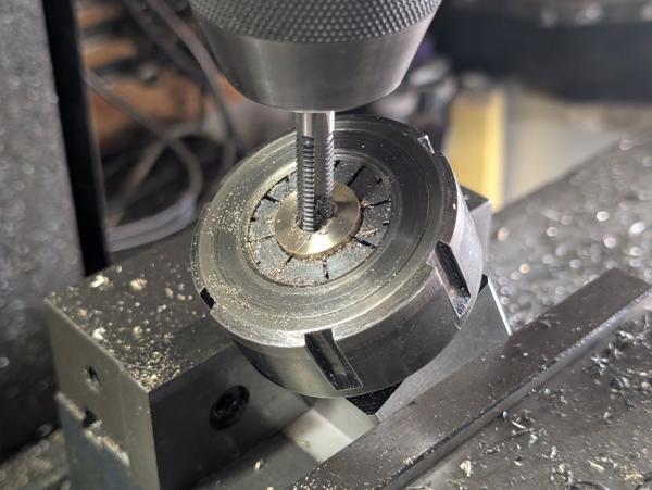
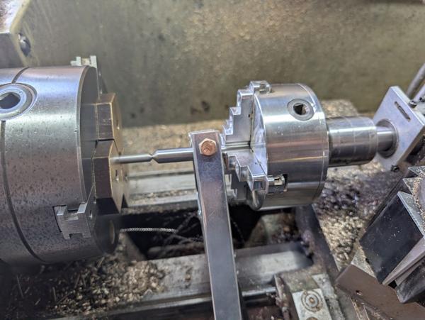
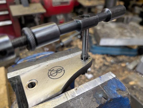
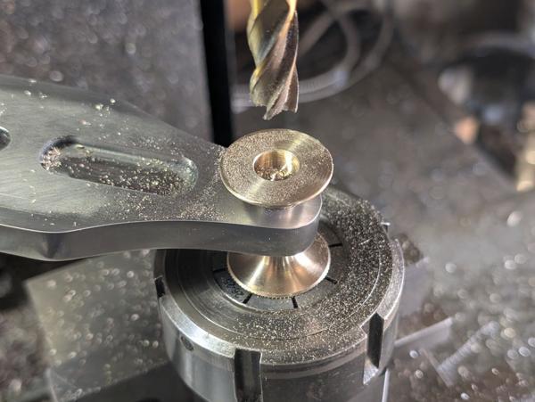
Unfortunately, I was a bit too aggressive with the mangling and it ended up a bit tighter than I would have liked: it would rotate but not very easily. There was a bit of excess screw thread so I decided to just have another go. To that end, I put the assembly in a collet block in the mill vice and milled out the end of the screw:
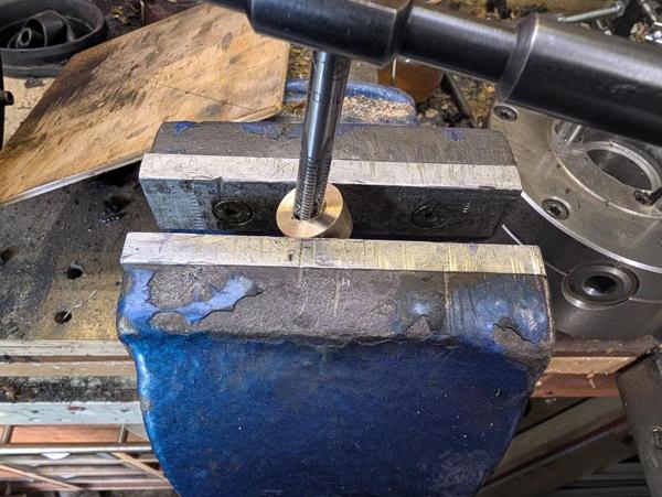
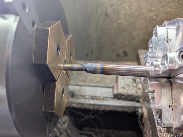
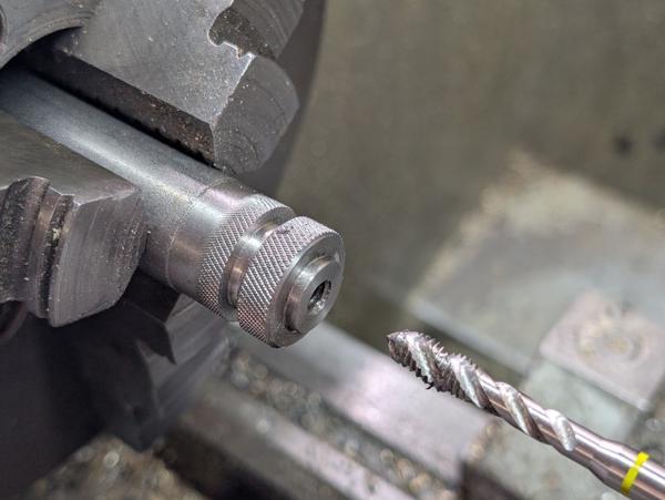
It could then go in the soft jaws on the lathe for a new tip:
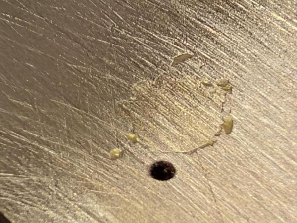
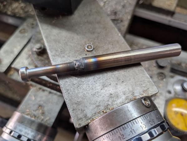
This time I was a bit more cautious and hit it just enough that it wouldn't come back out:
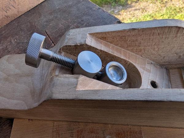
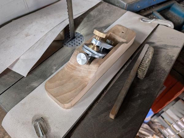
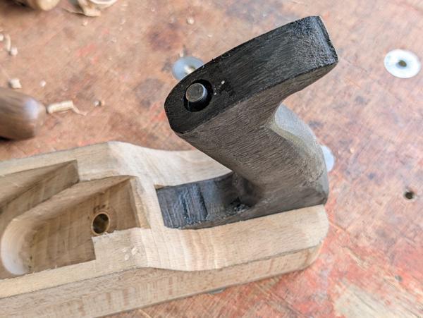
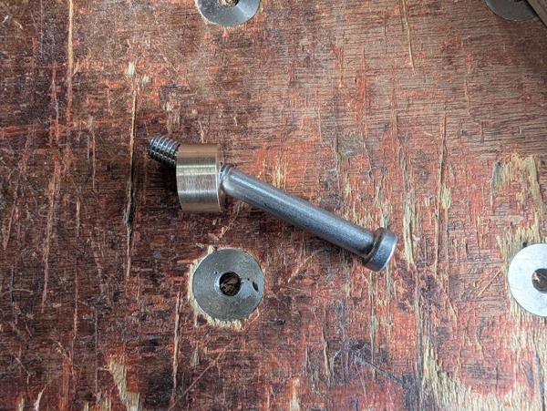
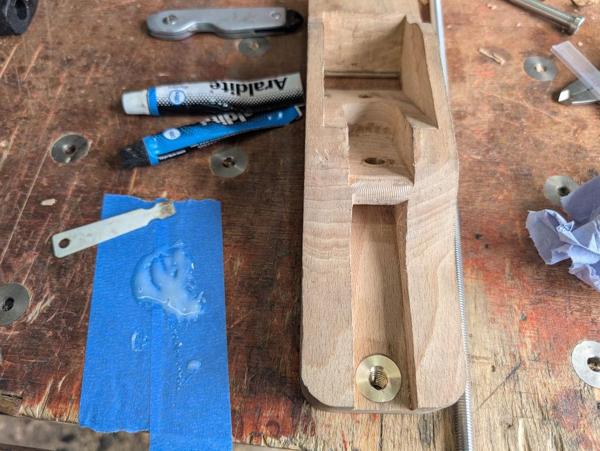
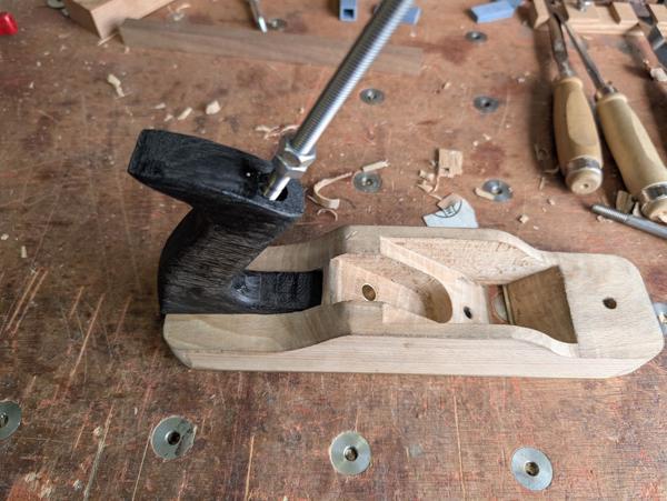
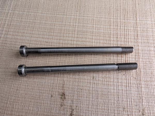
With that done (and the custom dual-thread threaded bar I made a few posts ago shortened slightly), I could do a trial assembly:
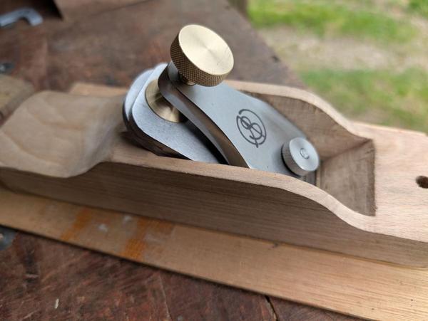
I'm really pleased with how that came out: it assembles easily and holds rigidly.
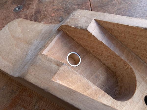
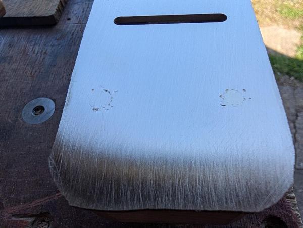
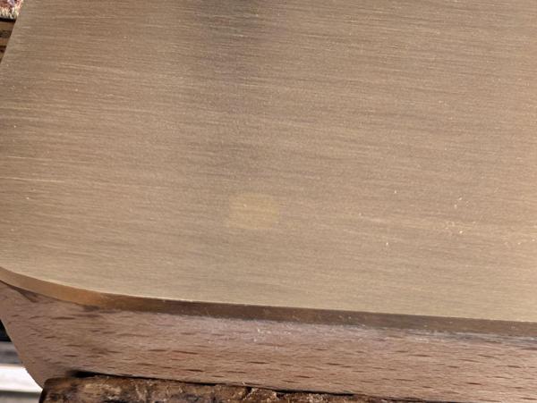
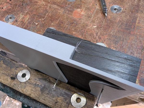
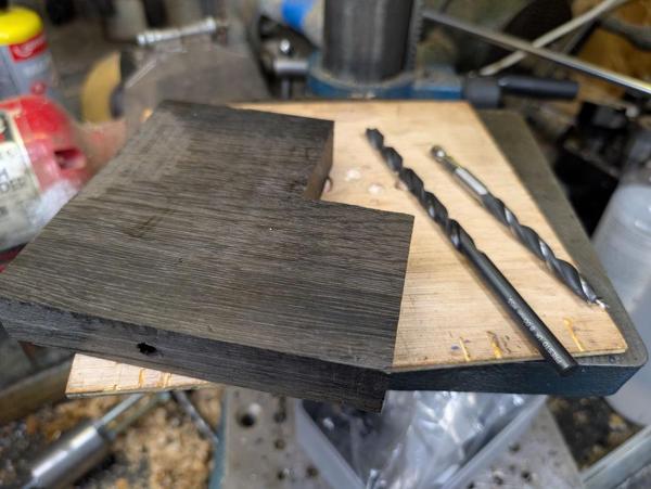
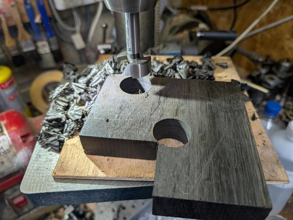
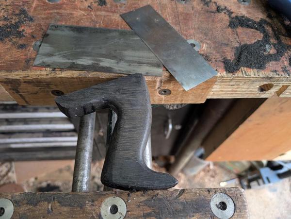
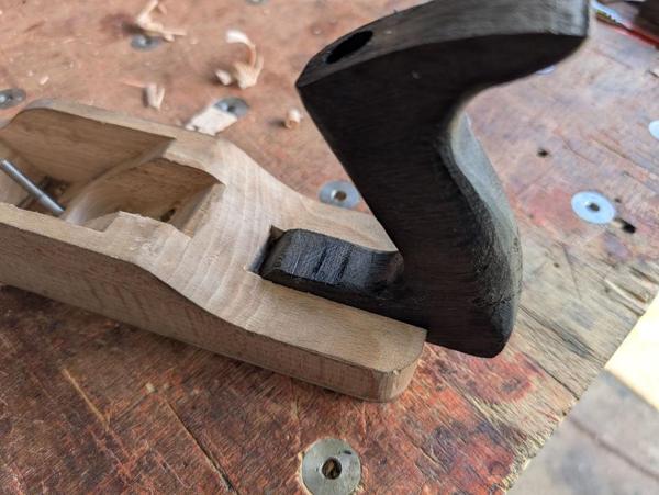
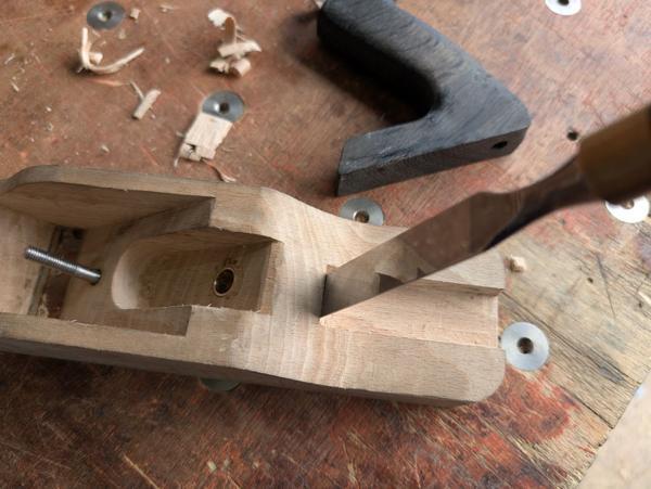
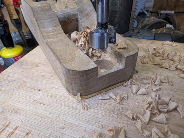
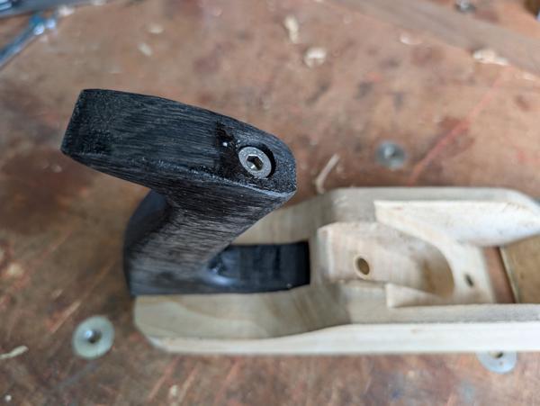
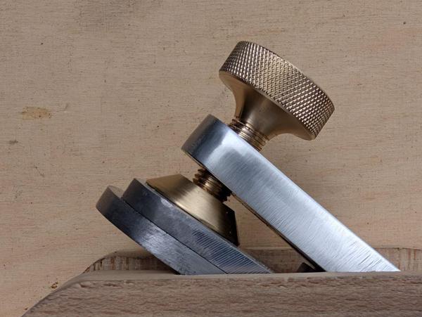
I mentioned early on that I was drilling the holes through the lever cap at an angle to account for its tilt. I think this photo shows what I was aiming for quite well:
After drilling it out 8.8 mm, I took it over to the bench vice and tapped M10 × 1.25.
I probably would have gone with M12 × 1.25 if I had the tap, but my collection "only" included M12 × 1, M12 × 1.5 and M12 × 1.75! I'm sure either of the finer pitch ones would have been okay, but the 1.25 mm pitch just seemed about right for this application.
Next up was a very simple knurled nut for the pivot screw:
That can be quite small as it is never properly tightened, just snugged lightly up against the lever cap before tightening the clamping screw.
I wanted a clamping arrangement a bit like the one on my Veritas low-angle smoothing plane. That has a large foot that presses down on the blade (there's no cap iron on the Veritas), spreading the force. I started by making the foot out of a bit of 32 mm brass, turning it down to 26 mm and then putting a 45° taper on it. It got drilled through 6 mm and counterbored 12 mm:
After parting off, it went in the home-made soft jaws for facing to length:
The clamping screw itself was made out of the same bar of brass. I used a tool with a big radius on it to reduce the diameter:
It didn't need a radius like that, I just did it because I felt like it.
The bigger section got knurled, the smaller section threaded M10 × 1.25 and the tip reduced and lightly spot drilled:
All of the above gave me this kit of parts:
On the Veritas lever cap, the foot is held in place with a circlip:
That is a very sensible option for a mass-produced part, but I'm only making one and I didn't have any circlips small enough. Instead, I assembled it all and used a punch to mangle the brass tip a bit so it couldn't go back through the hole:
Unfortunately, I was a bit too aggressive with the mangling and it ended up a bit tighter than I would have liked: it would rotate but not very easily. There was a bit of excess screw thread so I decided to just have another go. To that end, I put the assembly in a collet block in the mill vice and milled out the end of the screw:
It could then go in the soft jaws on the lathe for a new tip:
This time I was a bit more cautious and hit it just enough that it wouldn't come back out:
With that done (and the custom dual-thread threaded bar I made a few posts ago shortened slightly), I could do a trial assembly:
I'm really pleased with how that came out: it assembles easily and holds rigidly.
I mentioned early on that I was drilling the holes through the lever cap at an angle to account for its tilt. I think this photo shows what I was aiming for quite well: