A suggestion: get a few feet of 3-core mains cable, put a 3-pin plug on one end, fit a 3-Amp or 5-Amp fuse. Mark and note the position of all wires on the auxiliary transformer, and disconnect them. Connect Live to the screw terminal marked "240", Neutral to "0", and Earth to the frame. Switch on and measure the secondary AC voltages across 0 and 9, 0 and 27, and also from 0 to 220 on the primary. All assuming the fuse holds out of course...


You are using an out of date browser. It may not display this or other websites correctly.
You should upgrade or use an alternative browser.
You should upgrade or use an alternative browser.
Eland 160 just died!
- Thread starter Graham Francis
- Start date
Graham Francis
Member
- Messages
- 46
- Location
- Tenbury Wells
Thanks Eddie. I'll try this later. I'll also try putting a higher wattage 240V bulb across mains neutral in and the '0' auxillary transformer and see what happens. I was using a low energy bulb yesterday and whilst this lit, it wasn't going to be drawing much current. I'm interested to see the effect of placing a greater load at this point.
Graham Francis
Member
- Messages
- 46
- Location
- Tenbury Wells
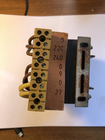
A suggestion: get a few feet of 3-core mains cable, put a 3-pin plug on one end, fit a 3-Amp or 5-Amp fuse. Mark and note the position of all wires on the auxiliary transformer, and disconnect them. Connect Live to the screw terminal marked "240", Neutral to "0", and Earth to the frame. Switch on and measure the secondary AC voltages across 0 and 9, 0 and 27, and also from 0 to 220 on the primary. All assuming the fuse holds out of course...
Hi Eddie. Connected the aux transformer up as above. Plugged 3-pin plug into mains socket and 3A fuse blew immediately with (of course) no voltage readings on the primary nor secondary terminals.
I then connected a 100W bulb across mains neutral in and the top '0' on the transformer connector block with the 240V supply reconnected. Plugged the welder in and bulb lit for a few seconds and then died away (previously a low energy bulb glowed constantly when I tried this). Disconnected everything and re-checked the voltage between neutral mains and '0' and I'm now getting circa 175V. Previously I was getting 240V across these two points.
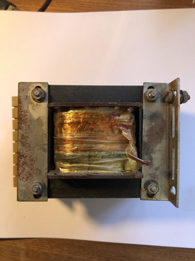
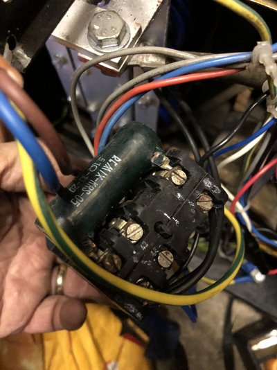
I'm now satisfied the aux transformer has failed, so will see if i can source a replacement. See photos of mine attached to this post.
Cheers
Graham
I've now got my ElandMIG 130 out of storage and have checked a few points:
Auxiliary transformer primary resistance:
"0" to "240" is 36.2 Ohms ( i.e. the mains-in section of the primary )
"0" to "220" is 33.1 Ohms ( the 220v output tapping for fan, contactor, and gas valve )
Between the 220 tapping and the 240 end of the winding: 3.3 Ohms
Running the wirefeed motor on 24v DC, it draws 1.1 Amps no-load, 1.6 Amps when heavily loaded with a gloved hand.
The "0" connector has one blue wire, the "220" has two black wires, the "240" has one red wire.
The fuse on the PCB is rated at 1 Amp, and it is wired between pins A3 and A4 of the board connector.
There are two relays on the PCB, and both have 12v DC coils. One runs the switched AC components, and the other brakes or enables the wirefeed motor drive. I previously thought that the 9 volt winding of the auxiliary transformer was not used. In fact, it is used to run these relays, via 4 x 1N400x diodes and a 220uF 25v smoothing capacitor on the PCB. The 9v AC supply is routed through a thermal sensor glued to the winding of the main welding transformer before it reaches the PCB ( on connector pins A1 and B1 ), so that a thermal overload would cause both relays to drop out.
Graham Francis
Member
- Messages
- 46
- Location
- Tenbury Wells
Thanks for the measurements @eddie49. Am waiting for my new transformer to arrive. In the meantime, I've placed 2A in-line fuses in the 220V supply to the GSV and Fan, plus the 27V and 9V outputs so as to protect the transformer windings and the PCB should there be anything going on that caused the breakdown in resistance on my original transformer. My machine now has 5 fuses including the fuse on the PCB. belt and braces hopefully!
Yes, I traced the 9V AC supply into the PCB and it's exactly the same as yours in terms of it supplying the diodes and smoothing capacitor. I've also checked both relays to make sure the relay contacts are not tracking to the energising coils and they are both fine in this respect. The bridge and smoothing capacitor sitting across the 27V AC feed also check out OK.
I'm hoping to have it all back together this weekend and will provide an update on status.
Cheers
Graham
Graham Francis
Member
- Messages
- 46
- Location
- Tenbury Wells
Oh dear...not good @eddie49 ! Fitted the new transformer, carefully checking and double checking everything was wired correctly (which it was). Turned it on and the fan ran up fine on the 220V tap (Checked that I was getting 220V off the tap and I was). Pressed the trigger on the torch and wire started feeding out along with the gas valve operating. Then after about a second or so, smoke started emitting from the black connector block 'device' where the mains input connects and the fuse in the plug blew. All other fuses I put in the 220V, 27V and 9V feeds were fine. I then removed these fuses, replaced the mains plug fuse and turned it back on. The fan started up OK, so I put each of the fuses back in and then pressed the trigger - and nothing! Neither the wire feed motor, nor the gas solenoid operated, but I could here at least one relay on the PCB operating when pressing the trigger.
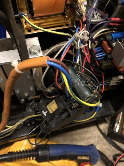
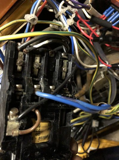
Hence I'm now a bit confused :-/. Why I should be getting what appeared to be some kind of short across this 'device' when it was fine before, I don't know. I'm also a bit confused at to what this device does (could it be a solenoid to switch between the mains in and the first 'welding current transformer'), given it appears to have a coil inside of it along with the large ceramic resistor (see photos). What I can see is that there are two blue wires coming out from underneath that supply a large transformer, but I don't know what internal connectivity there is from the mains in to the large transformer. With the power switched on without operating the trigger, I'm seeing 220V on the two grey wires that terminate on this unit. This is what I'd expect to see coming back via the GSV in the quiescent state. I'm guessing this should change to 0V with the trigger pressed (energising RL1 and connecting across contacts 4 and 5) as this provides a path back to neutral to operate the GSV.
I haven't investigated whether whether anything has now failed on the PCB, but hopefully not.
Any suggestions welcome, Eddie.
Many thanks
Graham
Graham Francis
Member
- Messages
- 46
- Location
- Tenbury Wells


Graham, I'm sorry to hear that things are not going too well, especially after the trouble you went to to source a new transformer.
The black device is the Contactor. It is a heavy-duty relay which supplies AC mains power to the primary of the main welding transformer. It has double-pole contacts, labelled MC1 1 and 2 in post #11 of this thread. The contactor operates every time the torch trigger is pressed. It parallels the action of the small relay RL1 on the PCB, but with more rugged construction and larger contacts for continuous high-current operation.There are also auxiliary normally-closed contacts which put the ceramic wire-wound bleeder resistor across the capacitor bank to discharge it, at the end of every weld operation.
The operating coil of the contactor is plainly marked 220v, so it should have been happy running in parallel with the gas valve off the "220" tap on the new transformer. It worked well before... Somehow it got too much voltage... but even direct mains about 230v should not have smoked it...
I'm sure this has something to do with the rewiring done by "TV repair man", but I'm not sure how he could have conjured up enough voltage to fry the coil.
A contactor is a very common industrial electrical component. Replacement coils are available, or the entire unit could be substituted with a modern equivalent. However, I think we have to first get to the root cause of the present fault. That may mean stripping out all the existing mains input circuitry and rewiring it in accordance with the diagram in post #11.
Graham Francis
Member
- Messages
- 46
- Location
- Tenbury Wells
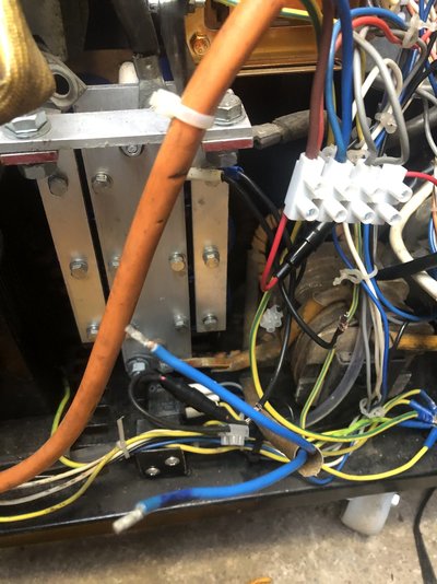
Hi Eddie. Many thanks for your message and for clarifying the Contactor device. I've removed it for testing and safely re-connected the mains live and neutral to the mains on/off switch and 240V input to the aux transformer and left everything disconnected and isolated. In the meantime, I've been diagnosing why the GSV and wire feed motor have stopped working. I'm getting 38.5V DC out of the bridge for the wire feed motor and 12V out of the bridge with discrete diodes for the PCB so this proves the output from the aux transformer is good. I'm also getting 220V now rather than 240V and the fan runs fine. I've lifted and tested TR3, the diodes and the capacitor supplying RL1 and RL2 and these all test out OK. For good measure, I also lifted and tested the Darlington Pair and these are both fine. I'm now suspecting the timer IC to have blown. I have a spare, so will try this tomorrow (Monday).
Back to the Contactor device......
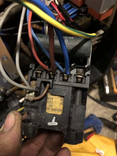
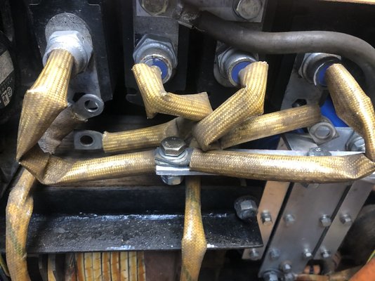
Putting my meter across the two blue wires from the connector that go to the current selector switch on the front panel, I'm getting zero resistance (apparent short) on all settings of the switch (wires disconnected from the Connector). I've also disconnected the rails to the main arc transformer and again, I'm getting zero resistance - see photos. I'm not sure what readings I should be getting at these points, but if I am getting a direct short across the wires feeding the panel switch, that might explain why the Contactor started smoking and the 13A fuse in the plug blew.
Going back to your previous post suggesting connecting mains into the aux transfer via a plug and 3A fuse, could I try this same approach across the two blue wires that feed the panel switch from the Contactor? If the fuse blows, then that would indicate there is a short somewhere, if not, then perhaps the Contactor itself has failed.
Be good to get your thoughts once again.
Graham
Back to the Contactor device......
Putting my meter across the two blue wires from the connector that go to the current selector switch on the front panel, I'm getting zero resistance (apparent short) on all settings of the switch (wires disconnected from the Connector). I've also disconnected the rails to the main arc transformer and again, I'm getting zero resistance - see photos. I'm not sure what readings I should be getting at these points, but if I am getting a direct short across the wires feeding the panel switch, that might explain why the Contactor started smoking and the 13A fuse in the plug blew.
Going back to your previous post suggesting connecting mains into the aux transfer via a plug and 3A fuse, could I try this same approach across the two blue wires that feed the panel switch from the Contactor? If the fuse blows, then that would indicate there is a short somewhere, if not, then perhaps the Contactor itself has failed.
Be good to get your thoughts once again.
Graham

Which relay on the PCB still operates when the torch trigger is pressed?In the meantime, I've been diagnosing why the GSV and wire feed motor have stopped working
The contacts of RL1 feed 220v, stepped-down off the "220" primary tapping of the auxiliary transformer, to the operating coil of the Contactor, which is most likely burned out, so it does not pull in. The 220v AC should be seen across the two coil terminal screw connections ( one with two grey wires, one with one black wire ). At the same time, the gas valve is in parallel with that component, so it should still operate.
If it is RL2 that still closes when the torch trigger is pressed, then the wirefeed motor should be running. It seems illogical that both the gas valve and the wirefeed motor don't work, since they have separate supplies and separate controls.
Thinking about how the 220v contactor coil might have been overloaded in the past:
The primary of the auxiliary transformer is being used as a step-down autotransformer, to run three 220v components ( the fan, gas valve, and contactor ) from a 240v mains input. If the connections to the 220 tap and the 240v far end of the winding were miswired, so that they were reversed, the 240v supply would be over-driving into a primary winding rated at only 220 volts, which would stress the transformer. If the 240v connection at the far end of the primary winding was then miss-wired to feed the three 220 volt components, their supply would in fact have a stepped-up value of 260 volts or more. This stress in the past could explain why the contactor coil has now burnt out.
Looking at your sketch of the original wiring in post #19, my theory about the 240v mains being fed in to what should have been the 220v output tapping on the auxiliary transformer may well be correct. Live goes to the "0" ( i.e. the start of the primary winding ), Neutral goes to the "220" tap via the main on/off switch, then the "240" far end of the winding feeds the fan, and the contactor and gas valve via the relay. The transformer was being over-driven, and it was stepping-up the feed to the 220v components.
The on/off switch is single-pole, with a neon. The switch contacts were wired in the Neutral line. Live should only be connected there to illuminate the neon.
The two thick blue wires from the Contactor go via the rotary power range switch to the primary of the main welding transformer. That winding will be a low resistance, perhaps two or three Ohms, but not zero. At low power ranges, the primary resistance will be higher, and it will decrease by fractions of an Ohm when stepping up to the maximum power settings. The double-pole contacts of the Contactor ( out of four available sets ), the power range switch, the main welding transformer and the associated wiring was not in doubt. I have assumed that it was the operating coil of the Contactor that started smoking. This could be confirmed by checking the resistance of that coil now. I would expect it should normally be about 300 Ohms. A potential short in the load across the contacts of the Contactor would be more likely to cause arcing at the contacts.
Contactors can usually be stripped fairly easily, and the contacts cleaned. If the two main sets of contacts that were in use are badly burned, the other two previously-unused ones may be used instead.
I've removed it for testing and safely re-connected the mains live and neutral to the mains on/off switch
Putting my meter across the two blue wires from the connector that go to the current selector switch on the front panel, I'm getting zero resistance (apparent short) on all settings of the switch (wires disconnected from the Connector). I've also disconnected the rails to the main arc transformer and again, I'm getting zero resistance - see photos. I'm not sure what readings I should be getting at these points, but if I am getting a direct short across the wires feeding the panel switch, that might explain why the Contactor started smoking and the 13A fuse in the plug blew.
Going back to your previous post suggesting connecting mains into the aux transfer via a plug and 3A fuse, could I try this same approach across the two blue wires that feed the panel switch from the Contactor? If the fuse blows, then that would indicate there is a short somewhere, if not, then perhaps the Contactor itself has failed.
The on/off switch is single-pole, with a neon. The switch contacts were wired in the Neutral line. Live should only be connected there to illuminate the neon.
The two thick blue wires from the Contactor go via the rotary power range switch to the primary of the main welding transformer. That winding will be a low resistance, perhaps two or three Ohms, but not zero. At low power ranges, the primary resistance will be higher, and it will decrease by fractions of an Ohm when stepping up to the maximum power settings. The double-pole contacts of the Contactor ( out of four available sets ), the power range switch, the main welding transformer and the associated wiring was not in doubt. I have assumed that it was the operating coil of the Contactor that started smoking. This could be confirmed by checking the resistance of that coil now. I would expect it should normally be about 300 Ohms. A potential short in the load across the contacts of the Contactor would be more likely to cause arcing at the contacts.
Contactors can usually be stripped fairly easily, and the contacts cleaned. If the two main sets of contacts that were in use are badly burned, the other two previously-unused ones may be used instead.
Graham Francis
Member
- Messages
- 46
- Location
- Tenbury Wells
Thanks once again for your comments @eddie49 I now have some great news, it's now all working nicely again 

 .
.
Let me explain....
Firstly, the non-operating GSV and wire feed motor when pressing the trigger.... . Given when I'd lifted and tested the various transistors and capacitors in the motor drive and spot and pulse timer circuitry they checked out OK, I had a hunch that the 556 dual timer may have blown as a result of the original aux transformer going AWOL, possibly raising the DC voltage beyond the limit of the IC (or perhaps blowing it due to a short). Remember, there was originally no fuse across the 9V AC input to the PCB (there is now). I replaced the IC, re-connected everything to the PCB and with the wires to the rotary power range switch disconnected from the Contactor, I turned the power back on. I pressed the trigger on the torch and both the wire feed motor and GSV operated. Not only this, the wire feed speed control was working correctly too.
Next up, I reconnected everything back up to the Contactor and on doing so, realised that the two black wires coming from each of the capacitor bank were connected to the same resistor terminal on the Contactor . I remembered that when I started investigating the faulty aux transformer, one of these wires came off the Contactor and I re-connected it where I thought it should have gone - obviously not in the right place! What I'd effectively done was to use the two black wires as the 50 ohm resistor as opposed to the resistor itself. The smoke was coming from the melting insulation on the wires and not the coil in the Contactor . That's a classic schoolboy error on my part . Re-connecting one of the black wires to the other side of the resistor, powering it back on and pressing the torch, there was no more smoke...phew.
Next up, I grabbed my welding mask, re-connected the gas and attacked some metal with it and to my surprise (and relief), I was welding again.
Everything now seems OK. There doesn't appear to have been any damage caused to the large smoothing capacitors and I've re-insulated the two black wires. I suspect that my meter wasn't able to accurately measure the low levels of resistance I should have seen back from the rotary power switch. Once we get some dry weather, I'll get back to welding the Land Rover chassis.
Apologies for all the smileys, but as you can imagine, I'm now jumping for joy. The thing is, you only learn how something works when it's broken. Having got it all working nicely again, I'm much more knowledgeable should I get any more issues in future.
The one downside of all of this is that a friend of mine who has a 20 year old Snap On MIG with a non-working wire feed motor has asked me to take a look at it. For some reason, he thinks I might be able to fix it for him. More on this in another post in the next few days .
.
Cheers
Graham
.Let me explain....
Firstly, the non-operating GSV and wire feed motor when pressing the trigger....
. Given when I'd lifted and tested the various transistors and capacitors in the motor drive and spot and pulse timer circuitry they checked out OK, I had a hunch that the 556 dual timer may have blown as a result of the original aux transformer going AWOL, possibly raising the DC voltage beyond the limit of the IC (or perhaps blowing it due to a short). Remember, there was originally no fuse across the 9V AC input to the PCB (there is now). I replaced the IC, re-connected everything to the PCB and with the wires to the rotary power range switch disconnected from the Contactor, I turned the power back on. I pressed the trigger on the torch and both the wire feed motor and GSV operated. Not only this, the wire feed speed control was working correctly too. Next up, I reconnected everything back up to the Contactor and on doing so, realised that the two black wires coming from each of the capacitor bank were connected to the same resistor terminal on the Contactor
. I remembered that when I started investigating the faulty aux transformer, one of these wires came off the Contactor and I re-connected it where I thought it should have gone - obviously not in the right place! What I'd effectively done was to use the two black wires as the 50 ohm resistor as opposed to the resistor itself. The smoke was coming from the melting insulation on the wires and not the coil in the Contactor . That's a classic schoolboy error on my part . Re-connecting one of the black wires to the other side of the resistor, powering it back on and pressing the torch, there was no more smoke...phew.Next up, I grabbed my welding mask, re-connected the gas and attacked some metal with it and to my surprise (and relief), I was welding again
.Everything now seems OK. There doesn't appear to have been any damage caused to the large smoothing capacitors and I've re-insulated the two black wires. I suspect that my meter wasn't able to accurately measure the low levels of resistance I should have seen back from the rotary power switch. Once we get some dry weather, I'll get back to welding the Land Rover chassis.
Apologies for all the smileys, but as you can imagine, I'm now jumping for joy. The thing is, you only learn how something works when it's broken. Having got it all working nicely again, I'm much more knowledgeable should I get any more issues in future.
The one downside of all of this is that a friend of mine who has a 20 year old Snap On MIG with a non-working wire feed motor has asked me to take a look at it. For some reason, he thinks I might be able to fix it for him. More on this in another post in the next few days
.Cheers
Graham


