


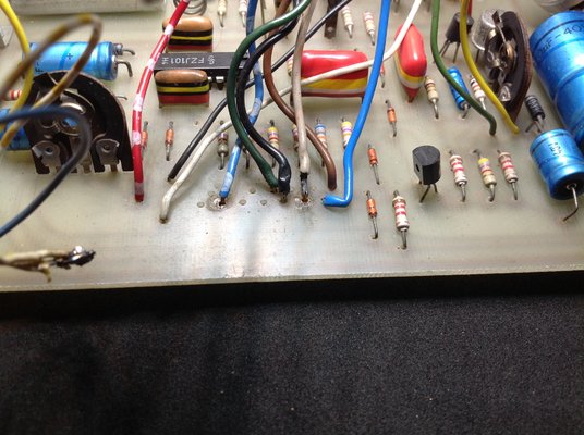
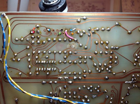
That's good news! Is that voltage measured at the yellow and black dots as per Test 3 or somewhere else?
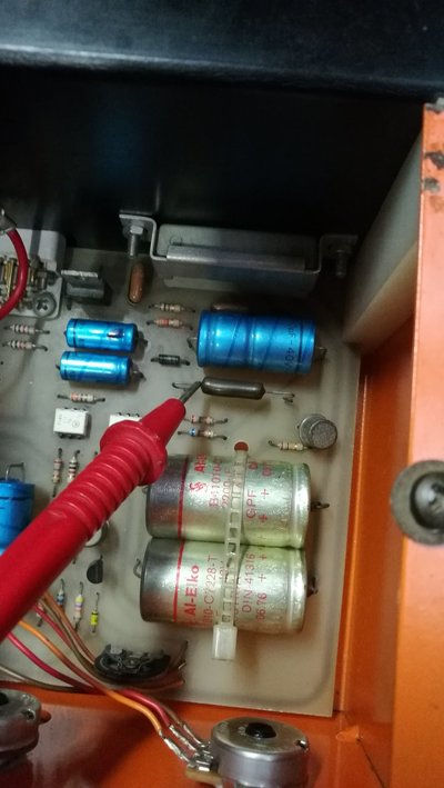
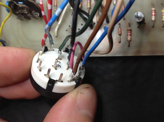
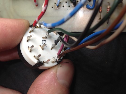
No it is measured at the wire connector inside the welder is will do the measurement again where you marked it.
And wil see what it does when I turn the 4 way mode switch.
 32v when the trigger is pressed is correct.
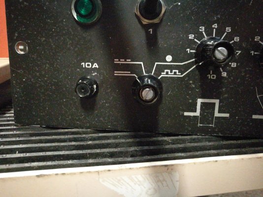

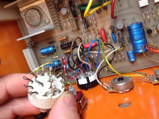
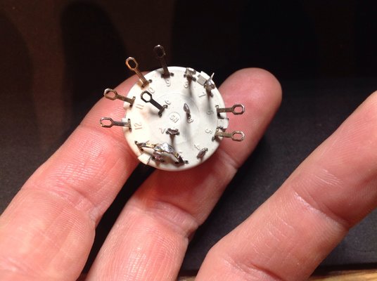
 ). Following on from what eddie49 said earlier, it's really good that you managed to find the schematic but it's also really frustrating that they didn't mark any of the components which makes it really difficult to follow. I'm now looking at the FZJ101 pin 5 issue because this should change voltage when you pull the trigger, I can see from the above schematic that the trigger input only goes to FZJ101 pin 5 when the 4 way mode switch is in two of those positions. But again it doesn't indicate on the schematic which switch position relates to which mode. And the symbols on the switch don't really give me a clue either!
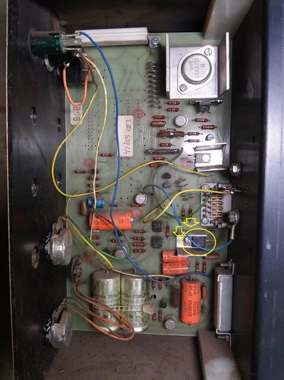


 And i realy appriciate the help and time you have put in to it


