


You are using an out of date browser. It may not display this or other websites correctly.
You should upgrade or use an alternative browser.
You should upgrade or use an alternative browser.
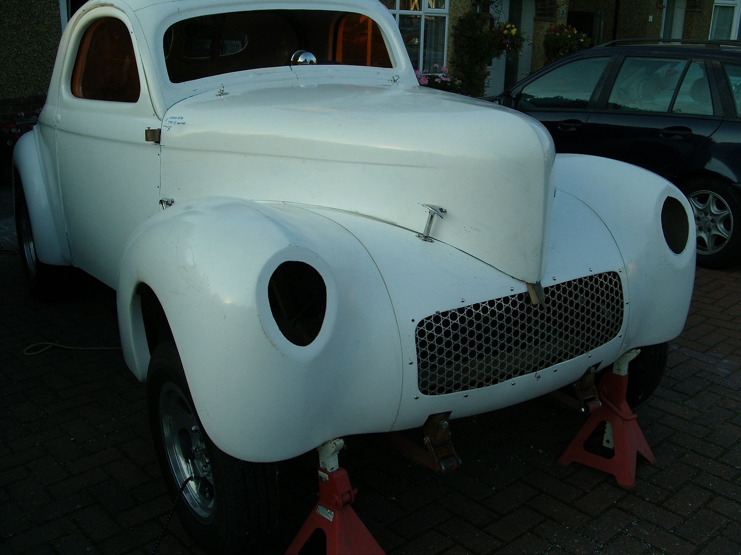
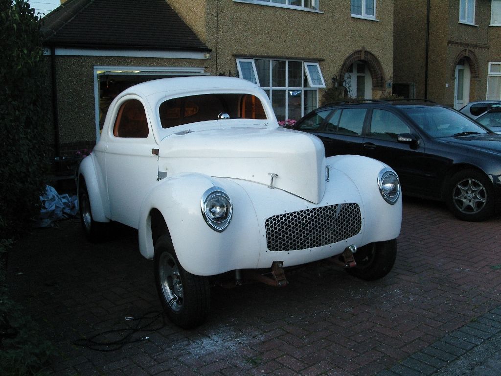
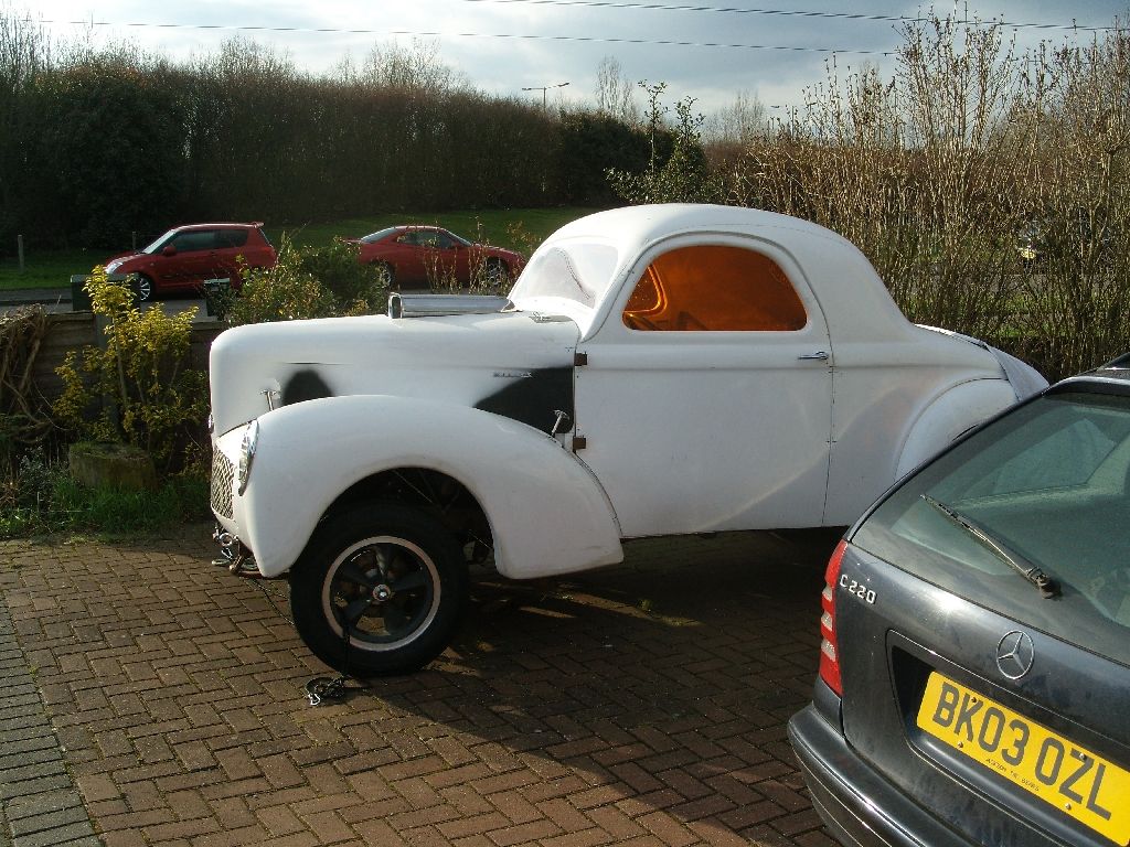
60's style Gasser Willys build
- Thread starter langy
- Start date

langy
langys rodshop
- Messages
- 6,095
- Location
- London
A short video of the doors working.
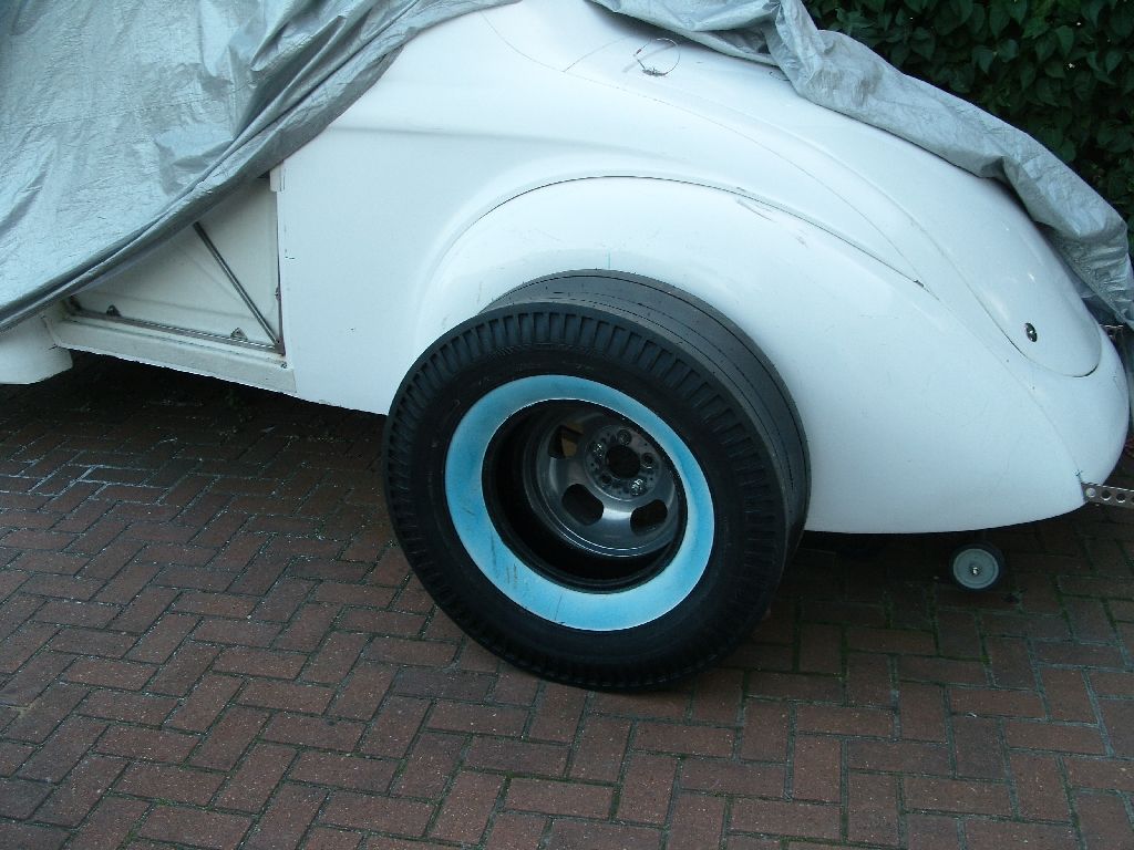
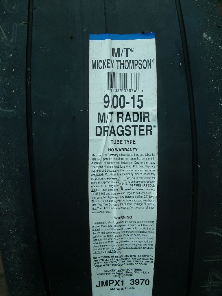
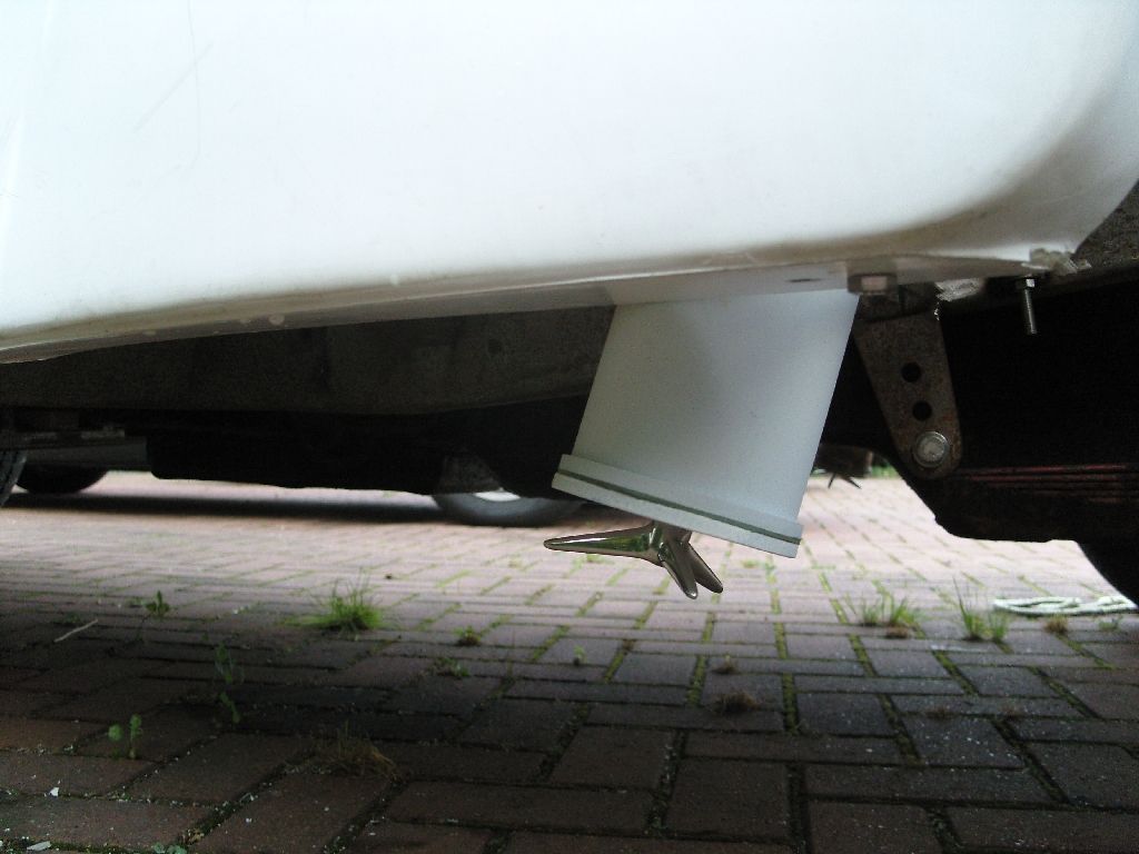
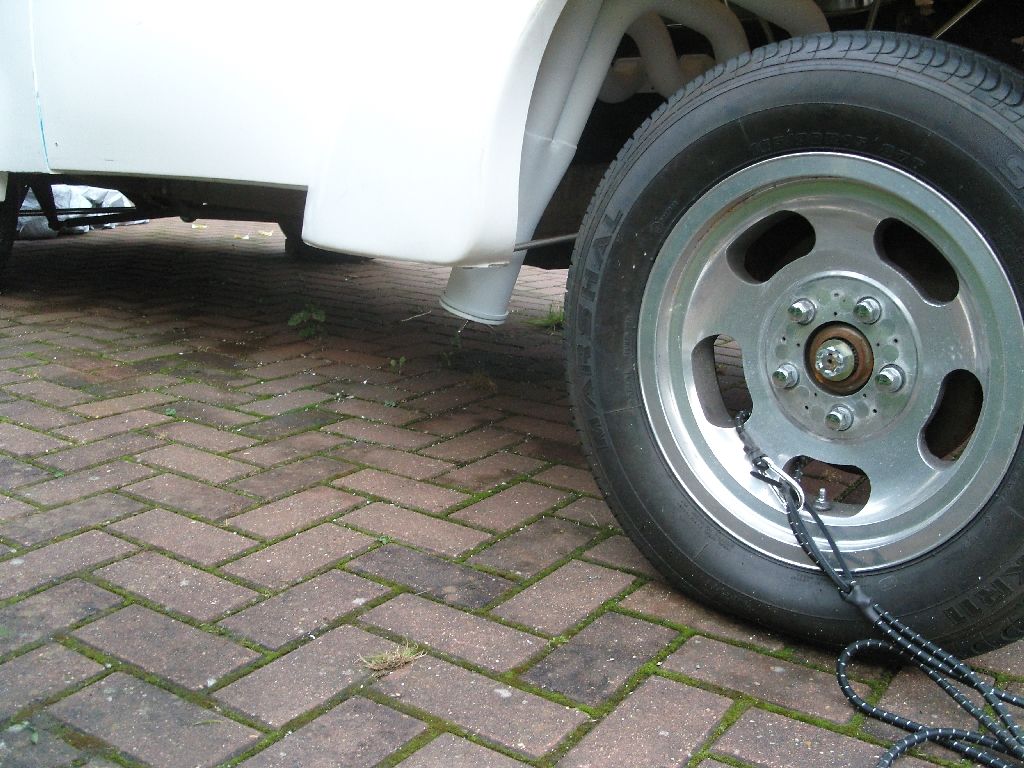
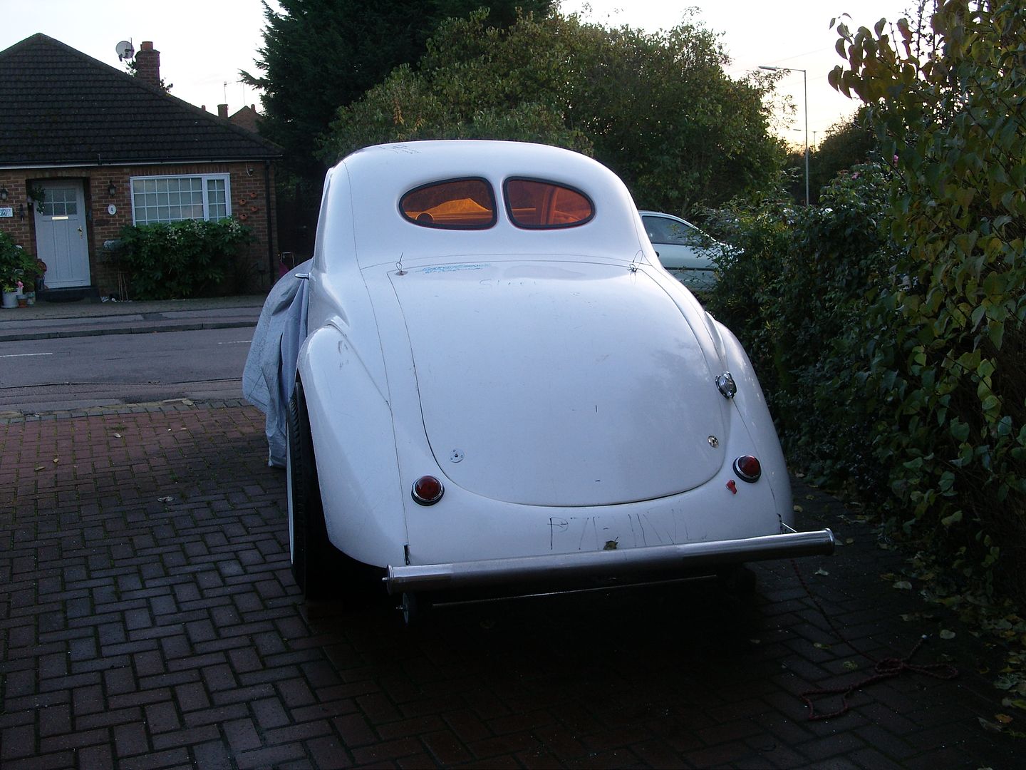
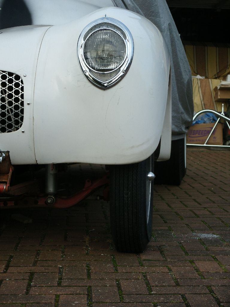
I'm all excited this morning as my rear tyres turned up, they are 900 x 15 Mickey Thomson pie crusts, 32" tall, I think a bit of trimming is needed on the rear arches

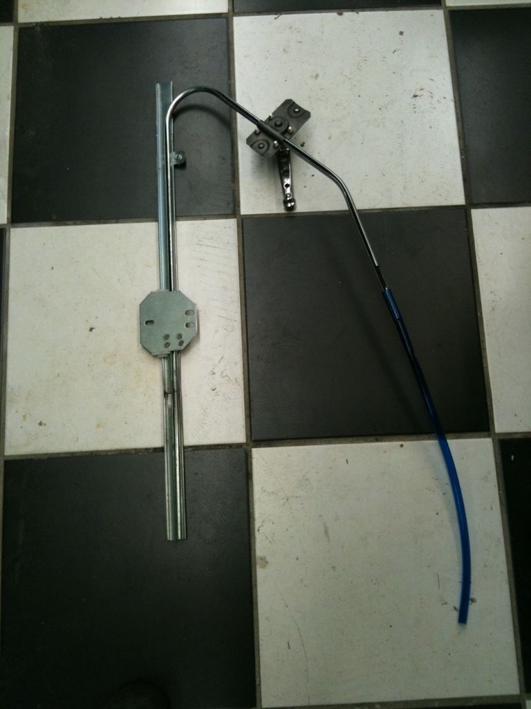
Well i sort of wasted a few hours last night modifying a Beetle winding mechanism to work in the Willys drivers door, Got it all done and dusted and realised i had done the passenger side
 got to wait till monday now for some more to arrive

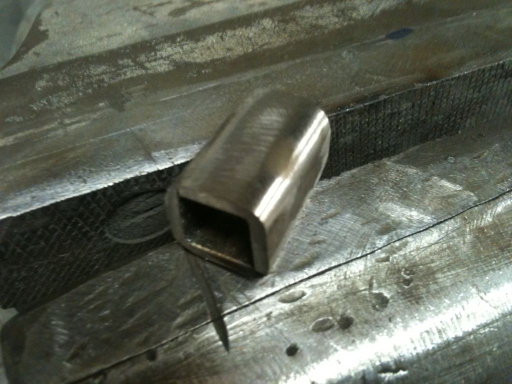
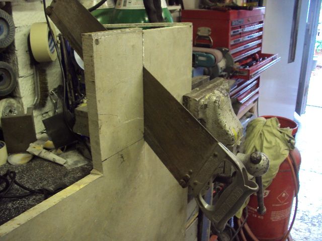
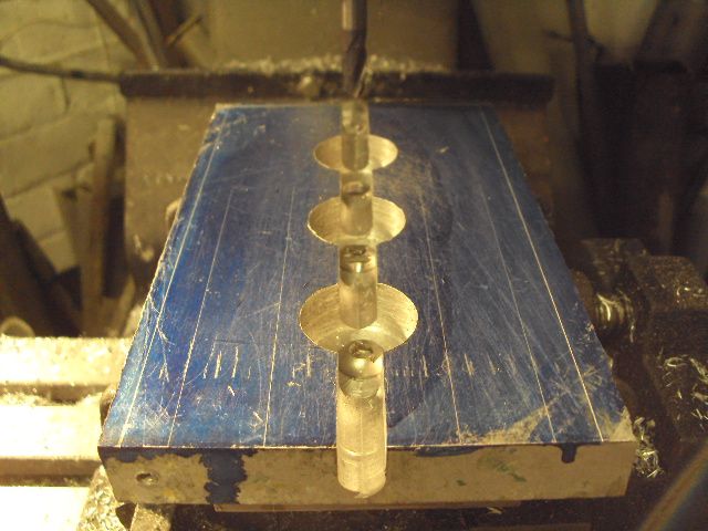
The beetle unit is really good and adaptable but needs modifying if the window travel is over 15" but its very easy to do, heres how i do it
This is where i cut and extend, I use an old unit cut up for bits.
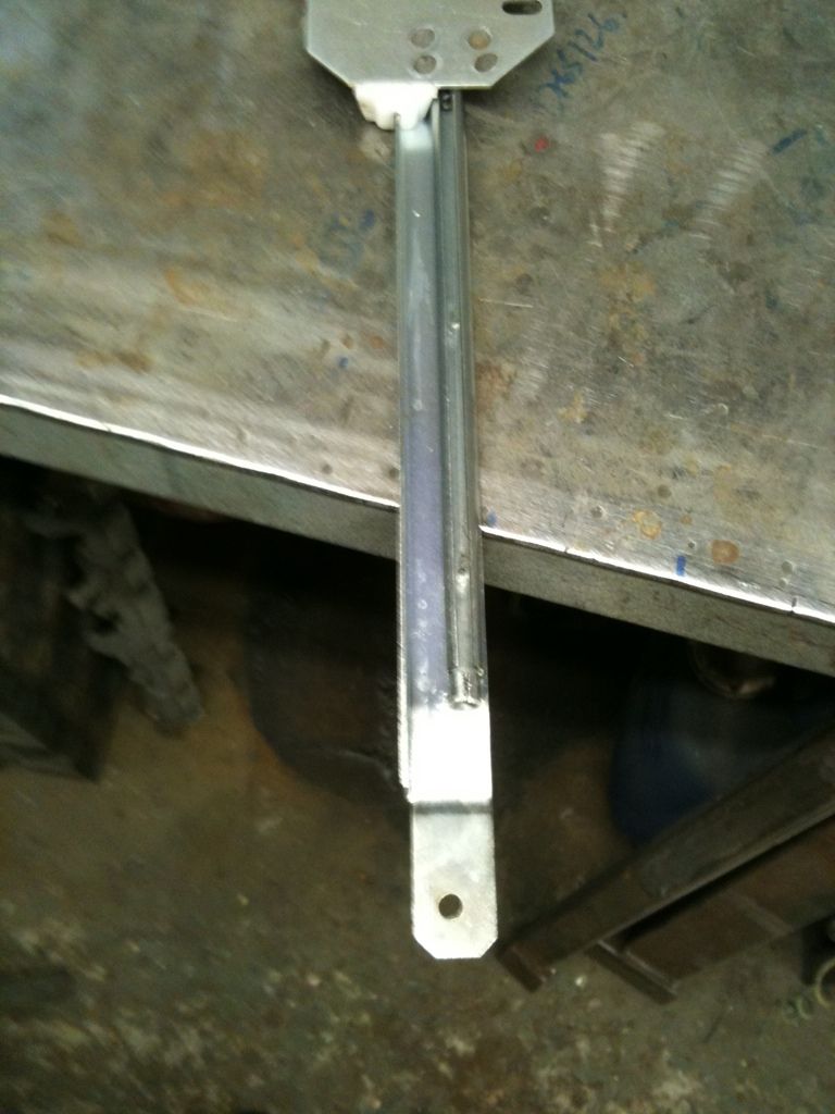
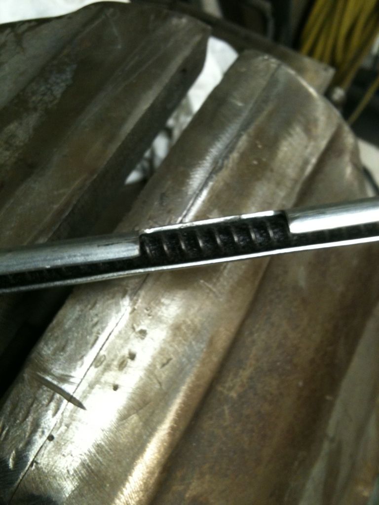
I slice the end off at the slot in the split tube
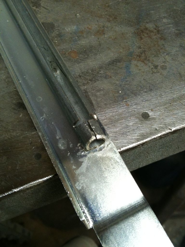
Then a piece is cut from an old unit for the extension
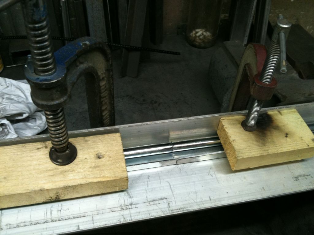
Everything is clamped to a piece of angle to keep it aligned, the surface needs to be ground clean for welding, Its not nice stuff to weld even when ground.
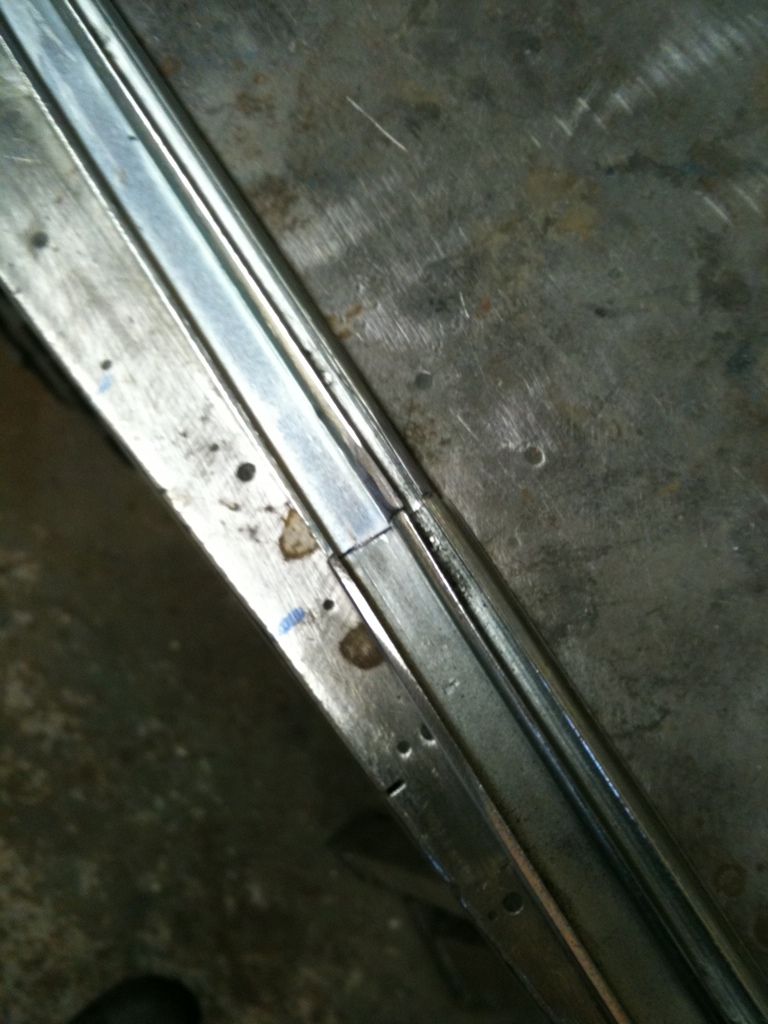
Here its welded and smoothed out, the joint needs to be smooth for the plastic runner to slide over it.
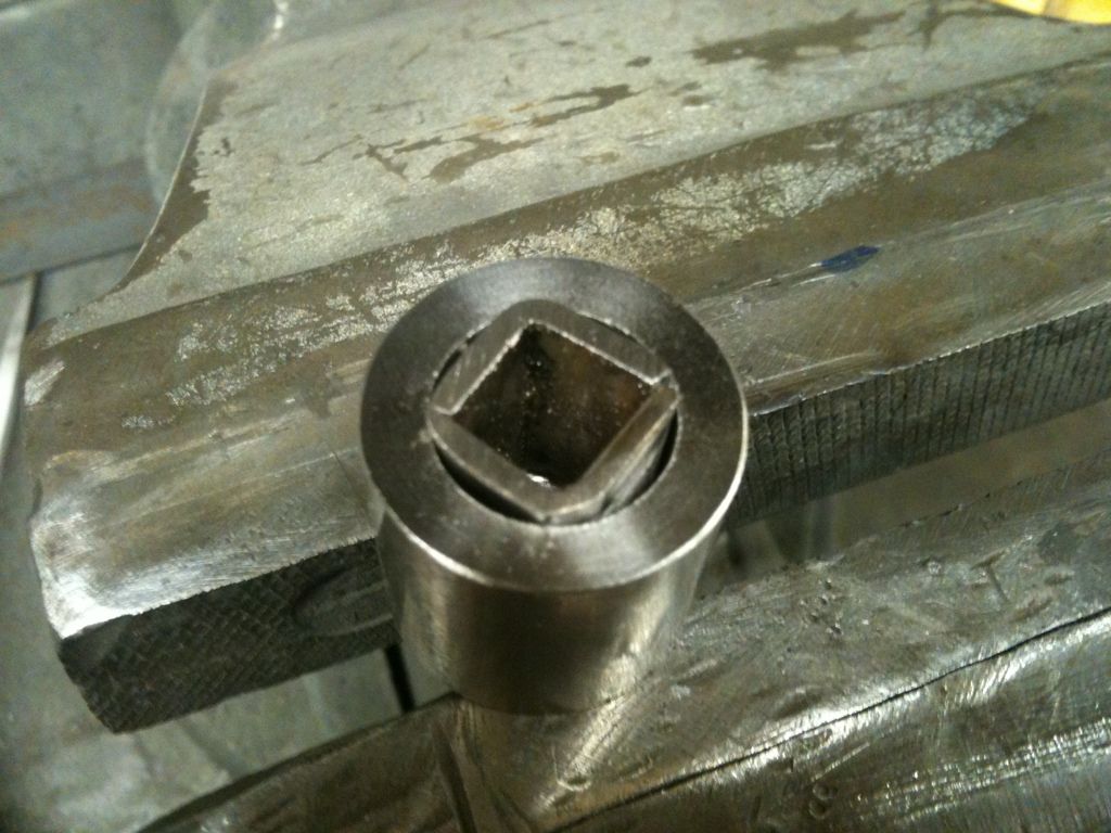
Next job was to move the winding gear, the rivets holding it together were drilled out and the gear housing split into 2 halves.
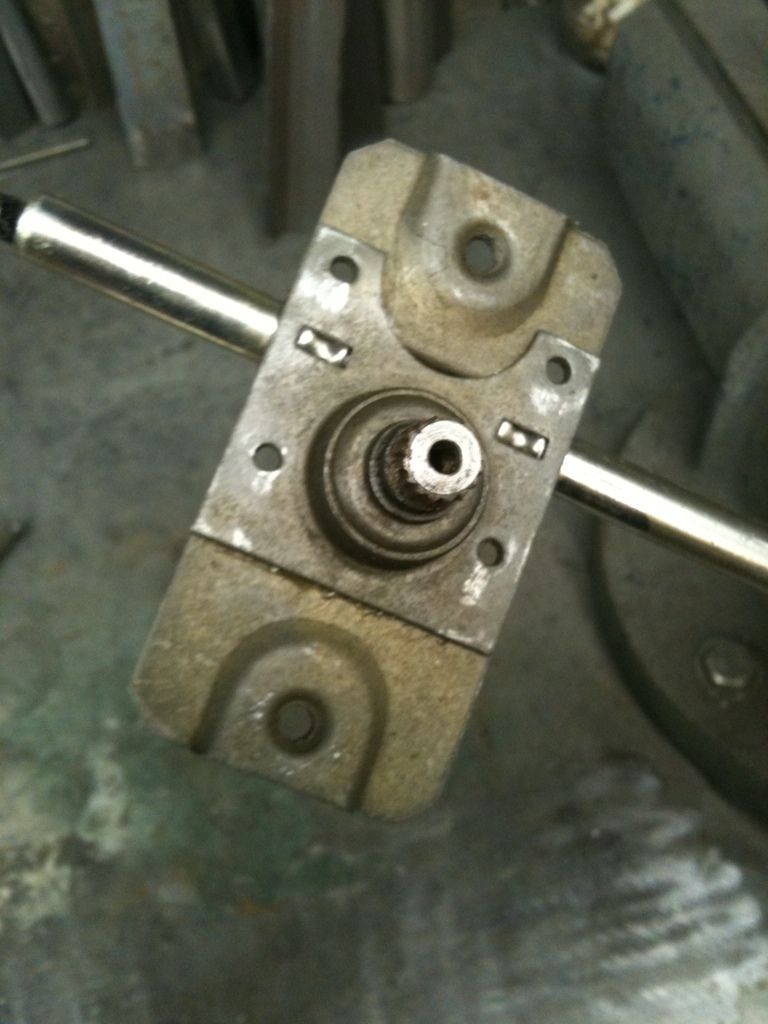
Then you just recut the slot that the gear sits in wherever else you need it. Cut with the cable removed.
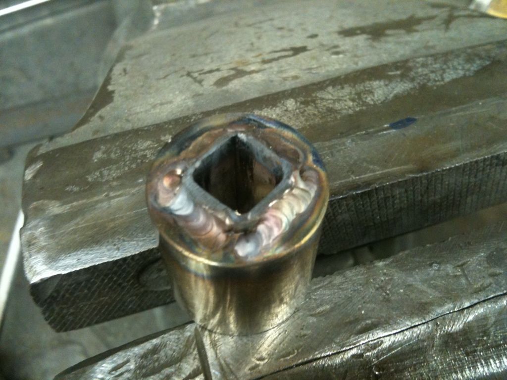
Then reassemble, final tweaking can be done by carefully bending the tube the cable runs in.
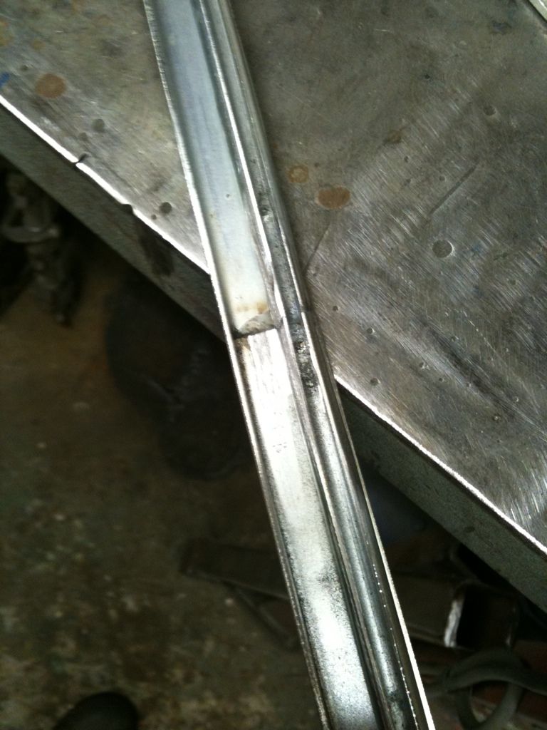
A piece of plastic tube is slid over the end to keep the inner cable clean.
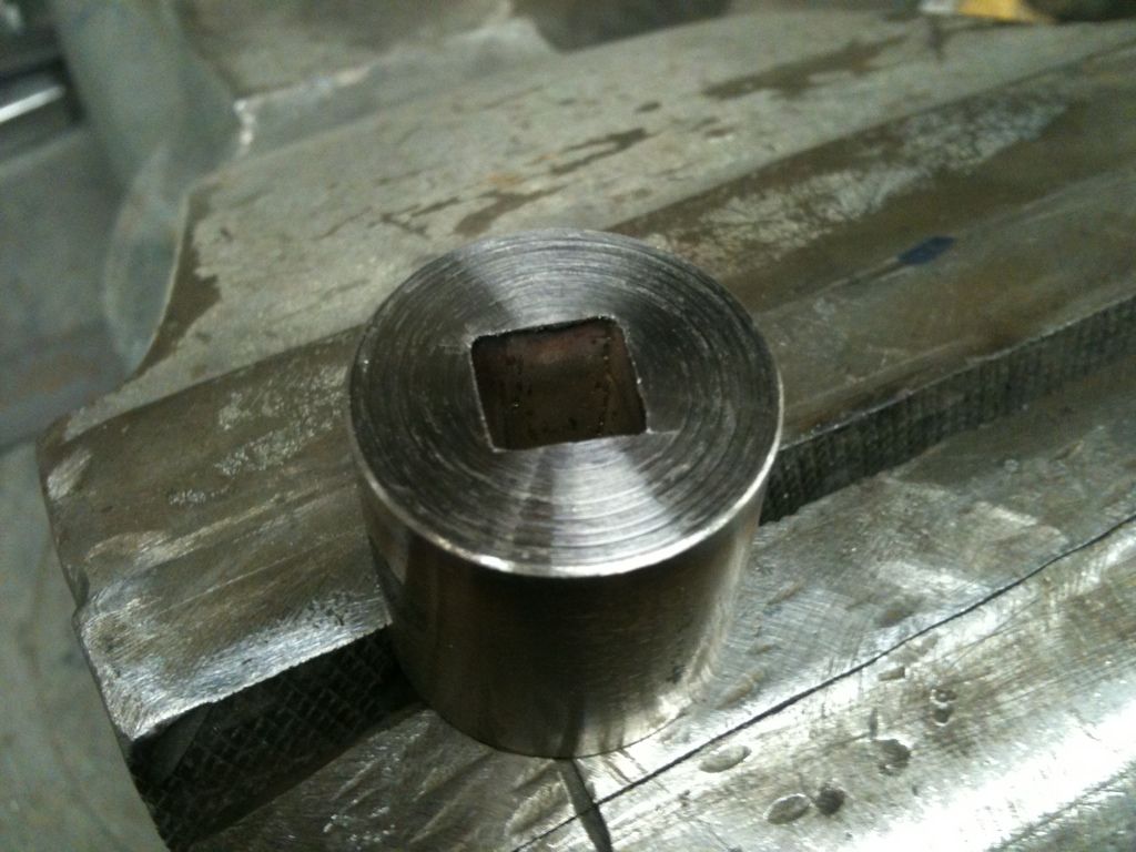
Heres the completed modified mechanism ready to bolt in.
I'm all excited this morning as my rear tyres turned up, they are 900 x 15 Mickey Thomson pie crusts, 32" tall, I think a bit of trimming is needed on the rear arches
Well i sort of wasted a few hours last night modifying a Beetle winding mechanism to work in the Willys drivers door, Got it all done and dusted and realised i had done the passenger side
The beetle unit is really good and adaptable but needs modifying if the window travel is over 15" but its very easy to do, heres how i do it
This is where i cut and extend, I use an old unit cut up for bits.
I slice the end off at the slot in the split tube
Then a piece is cut from an old unit for the extension
Everything is clamped to a piece of angle to keep it aligned, the surface needs to be ground clean for welding, Its not nice stuff to weld even when ground.
Here its welded and smoothed out, the joint needs to be smooth for the plastic runner to slide over it.
Next job was to move the winding gear, the rivets holding it together were drilled out and the gear housing split into 2 halves.
Then you just recut the slot that the gear sits in wherever else you need it. Cut with the cable removed.
Then reassemble, final tweaking can be done by carefully bending the tube the cable runs in.
A piece of plastic tube is slid over the end to keep the inner cable clean.
Heres the completed modified mechanism ready to bolt in.
langy
langys rodshop
- Messages
- 6,095
- Location
- London
<HR style="BACKGROUND-COLOR: #d1d1e1; COLOR: #d1d1e1" SIZE=1><!-- / icon and title --><!-- message -->
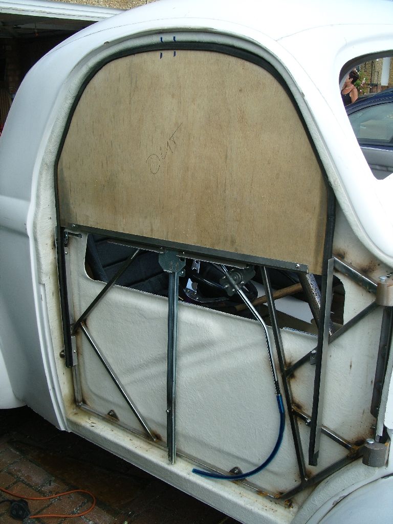
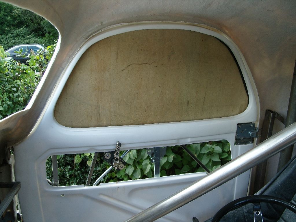
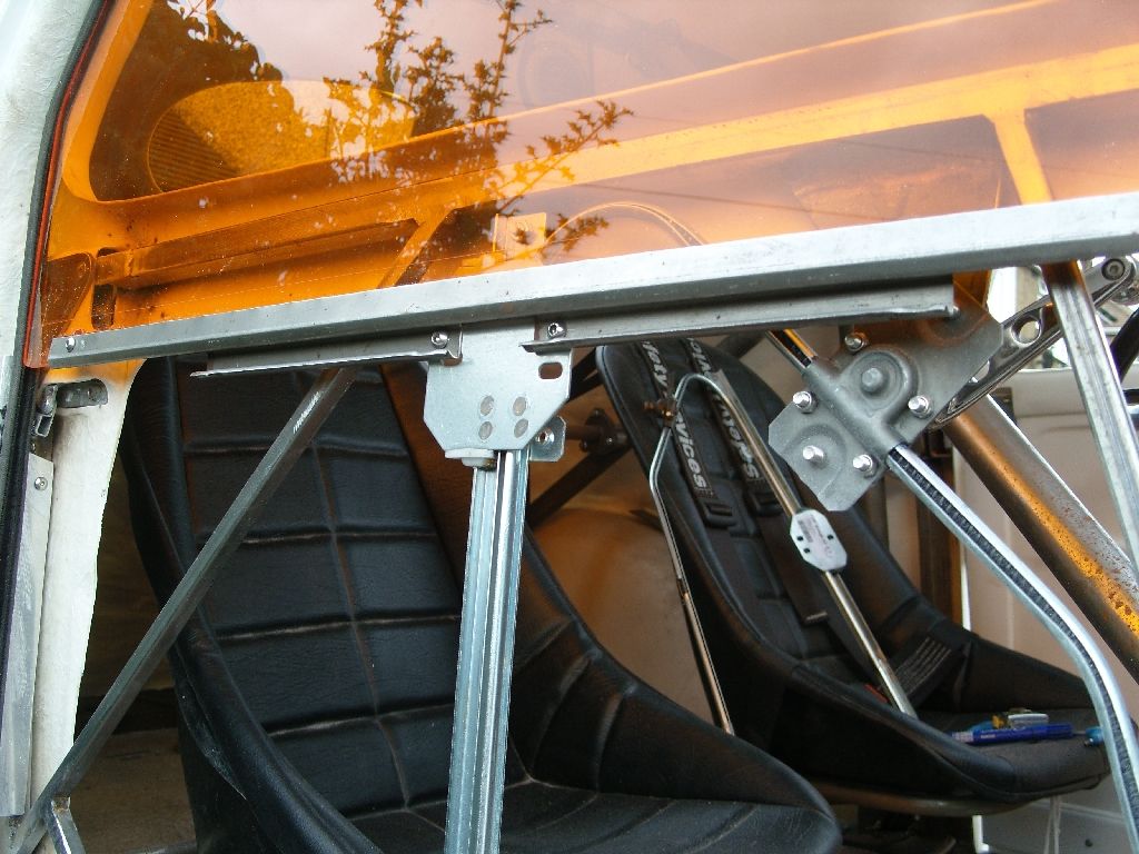
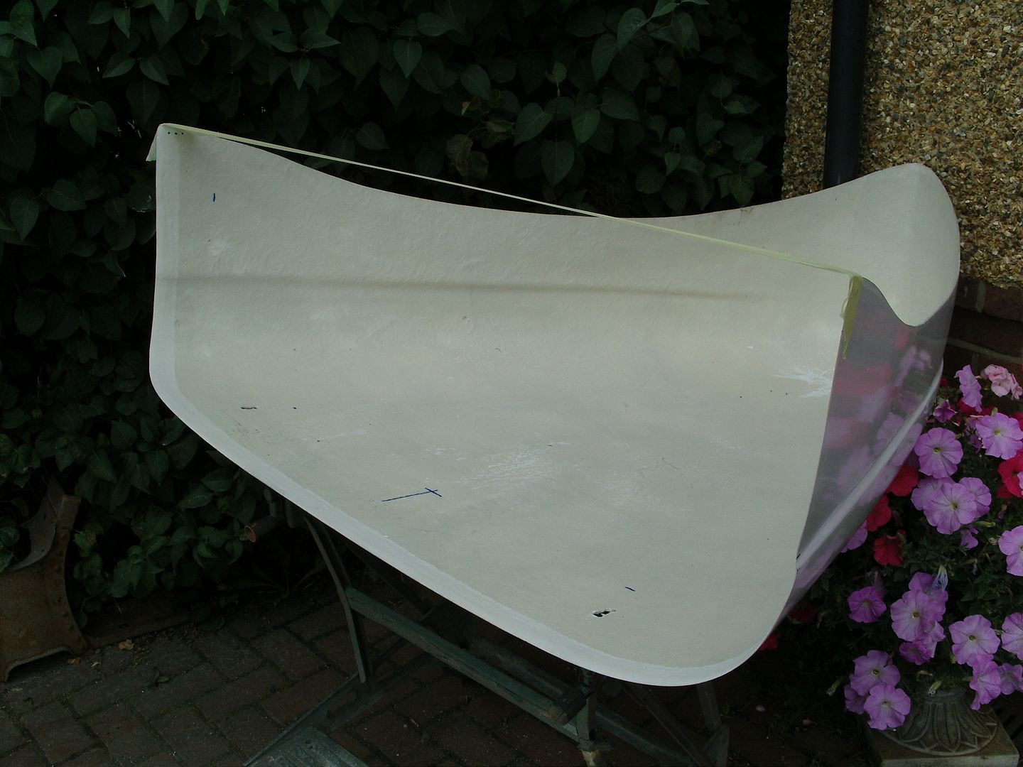
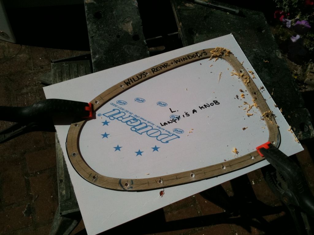
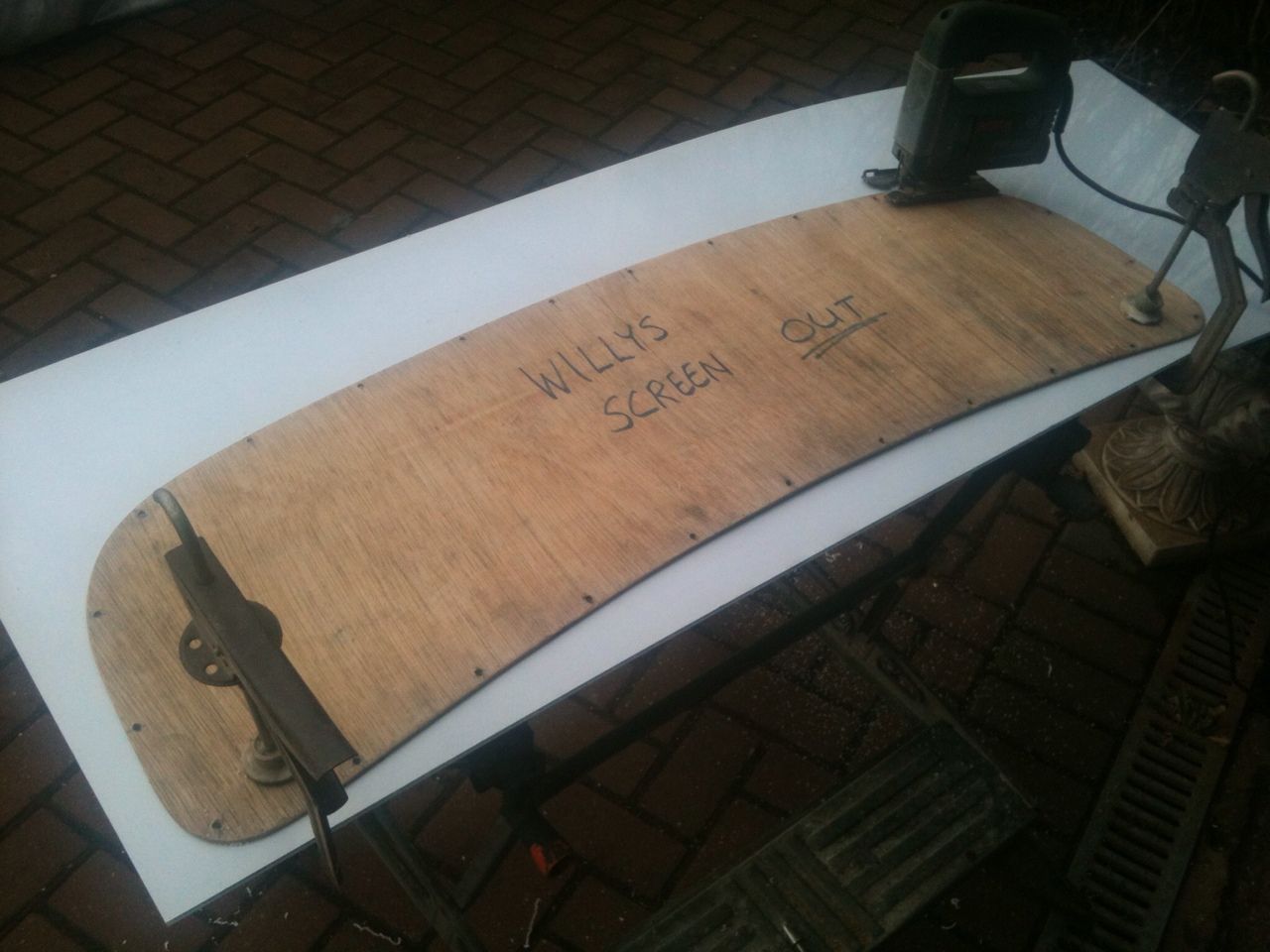
Weathers been nice the last few evenings so managed to get the windows sorted, The winding mechanisms turned up on monday so that gave me the chance to make up a 3/16" ply window template and then i could install the winders.
The next morning the acrylic i ordered for my windows turned up, I ordered this from Trent plastics on saturday morning and it arrived tuesday am, excellent service i thought.
The ply was removed and used for the template, this acrylic is so easy to cut with a jigsaw, it onlys requires a light sanding to acheive a perfect edge, also drills real well and clean.
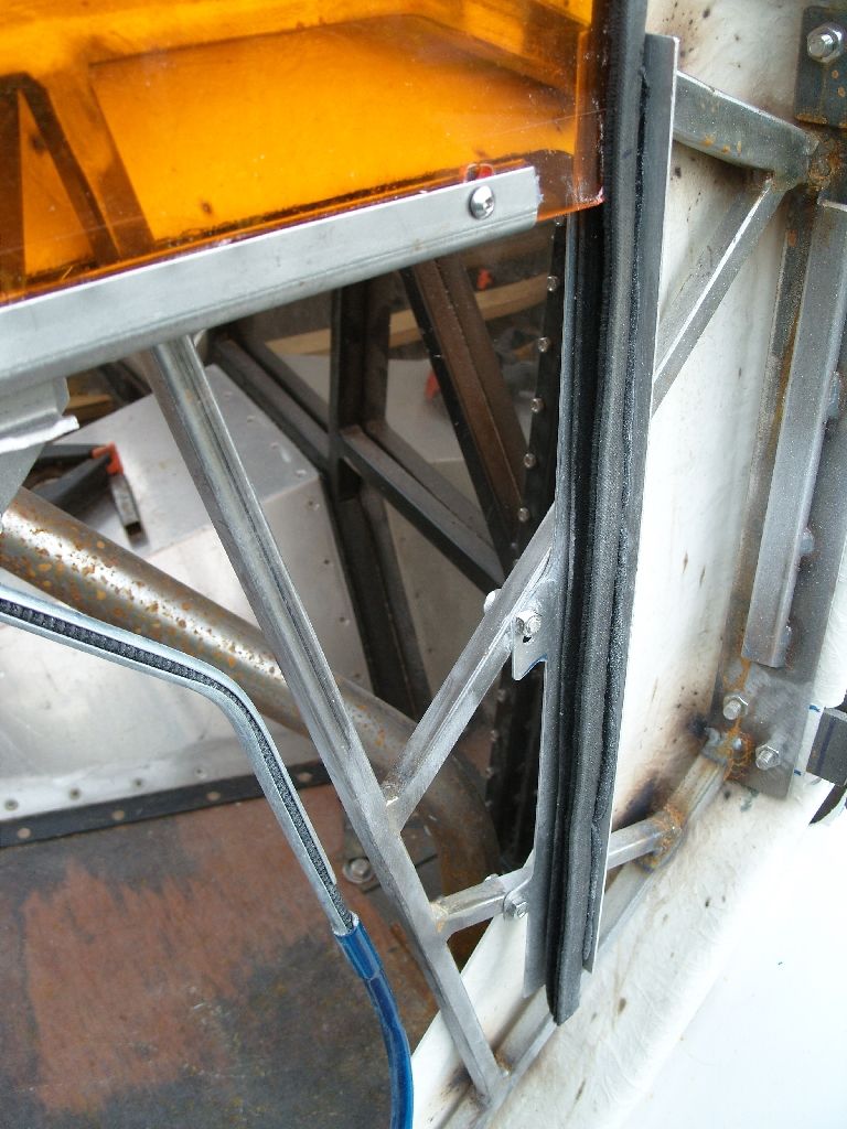
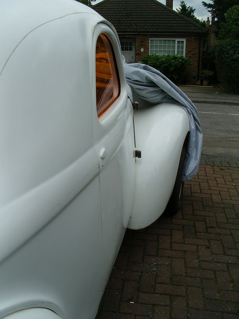
I went with 5mm (3/16") as the only other choice was 3mm which was too flexible. colour is orange.
For window channel i used the universal cloth covered stuff, it comes in a coil and is simple to bend to shape and is fairly rigid, this is held in place with polyeurathane adhesieve sealant once the doors are painted, at the moment its only held in place by the 2 aluminium sections i made up, they are bolted to the steel tube frame.
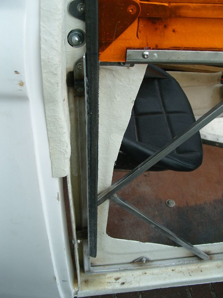
The window channel that holds the bottom of the window was a pair i had hanging around, havn't a clue what they are from but they could also be easily fabbed as they are just a U section with a couple of brackets welded on.
Cut out the acrylic window and bolted it into place with some small 5mm button head bolts & nylok nuts.
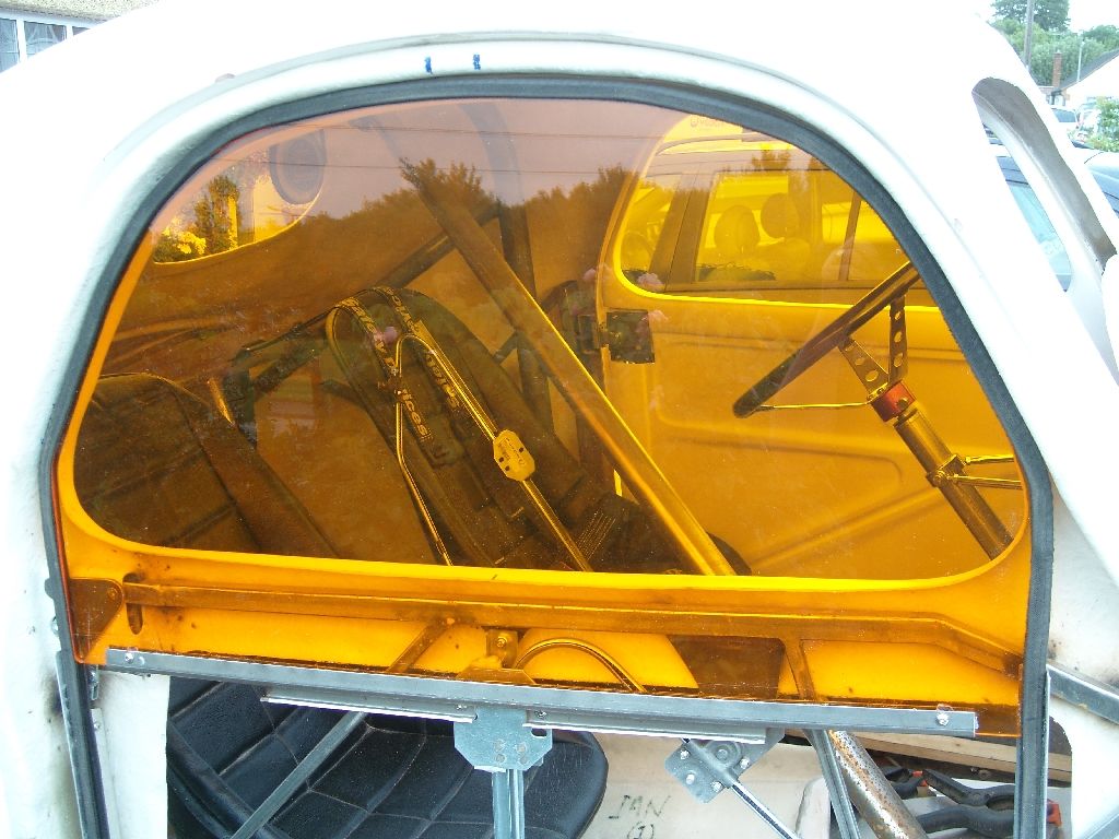
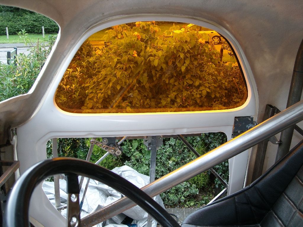
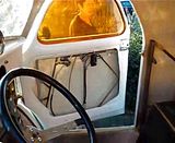
They are all dry fitted at the moment but wind up & down real nice and smooth, with a bit of use they should bed in nicely. heres a short video of them in operation.
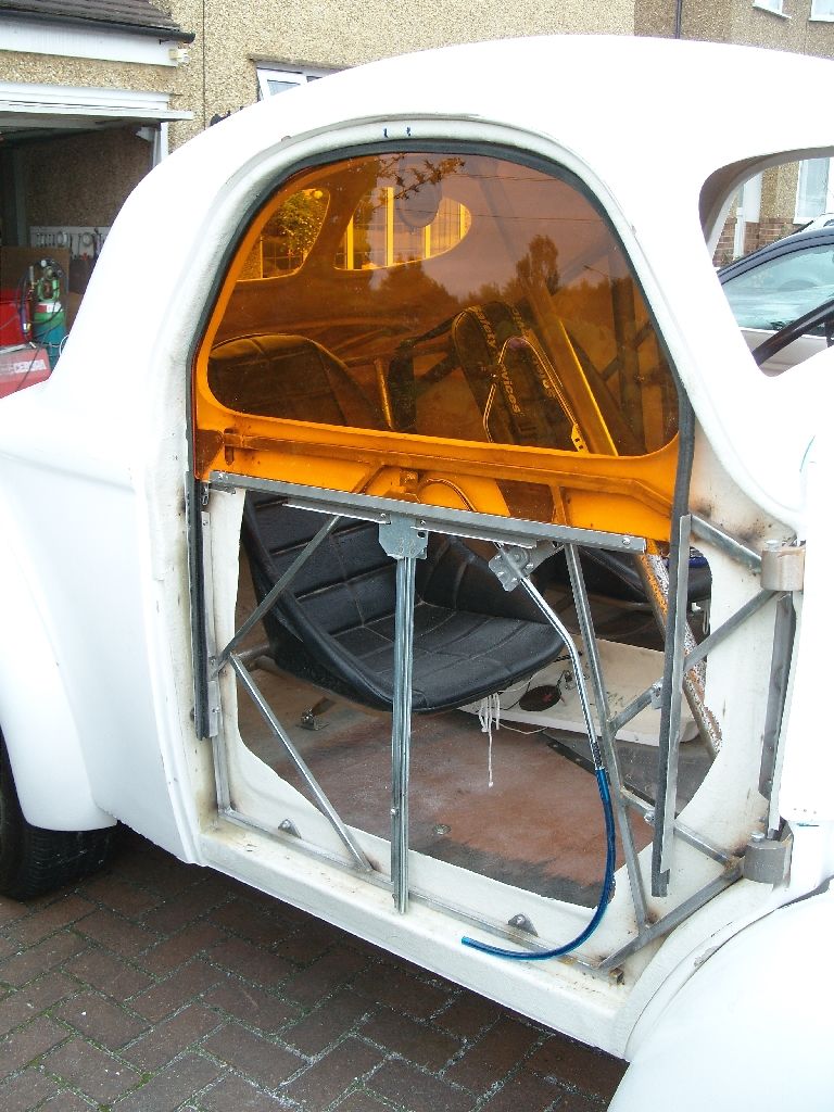
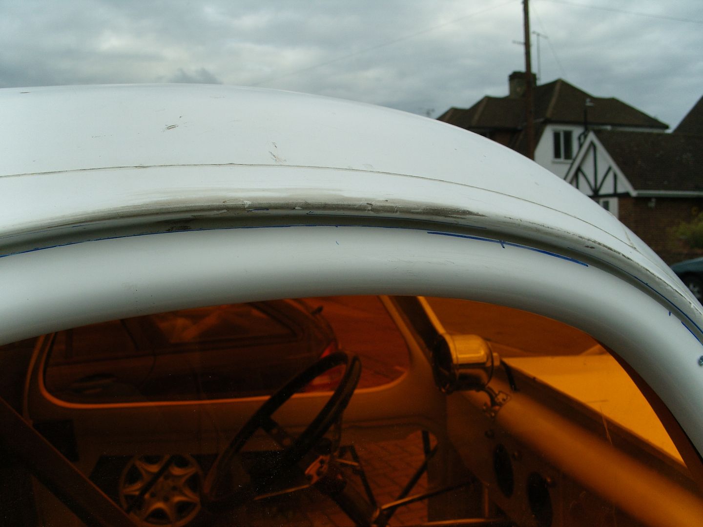
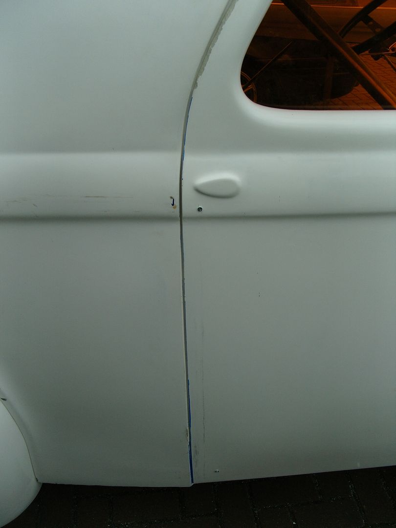
Started fettling the door skins last night, with a bit of trimming they more or less went straight on, Held in place with a few small screws at the moment, hopefully bond them on tomorrow. Just a bit of gapping needed and we should be good to go.
Weathers been nice the last few evenings so managed to get the windows sorted, The winding mechanisms turned up on monday so that gave me the chance to make up a 3/16" ply window template and then i could install the winders.
The next morning the acrylic i ordered for my windows turned up, I ordered this from Trent plastics on saturday morning and it arrived tuesday am, excellent service i thought.
The ply was removed and used for the template, this acrylic is so easy to cut with a jigsaw, it onlys requires a light sanding to acheive a perfect edge, also drills real well and clean.
I went with 5mm (3/16") as the only other choice was 3mm which was too flexible. colour is orange.
For window channel i used the universal cloth covered stuff, it comes in a coil and is simple to bend to shape and is fairly rigid, this is held in place with polyeurathane adhesieve sealant once the doors are painted, at the moment its only held in place by the 2 aluminium sections i made up, they are bolted to the steel tube frame.
The window channel that holds the bottom of the window was a pair i had hanging around, havn't a clue what they are from but they could also be easily fabbed as they are just a U section with a couple of brackets welded on.
Cut out the acrylic window and bolted it into place with some small 5mm button head bolts & nylok nuts.
They are all dry fitted at the moment but wind up & down real nice and smooth, with a bit of use they should bed in nicely. heres a short video of them in operation.
Started fettling the door skins last night, with a bit of trimming they more or less went straight on, Held in place with a few small screws at the moment, hopefully bond them on tomorrow. Just a bit of gapping needed and we should be good to go.
langy
langys rodshop
- Messages
- 6,095
- Location
- London
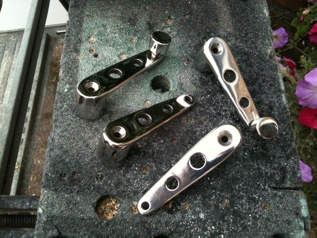
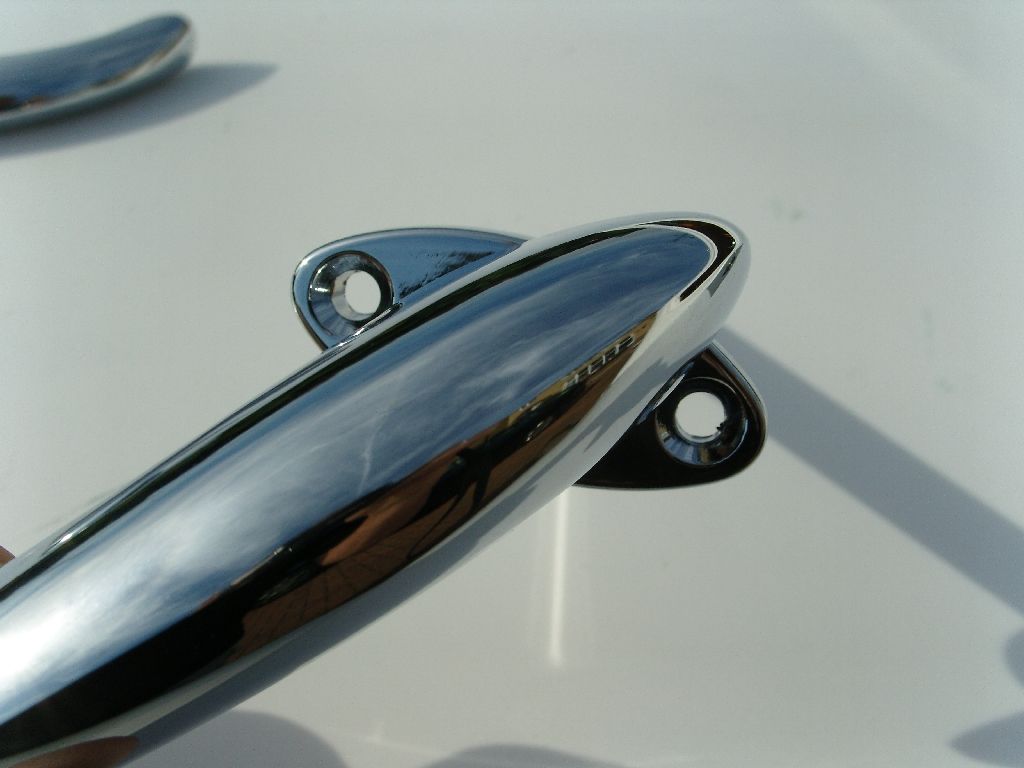
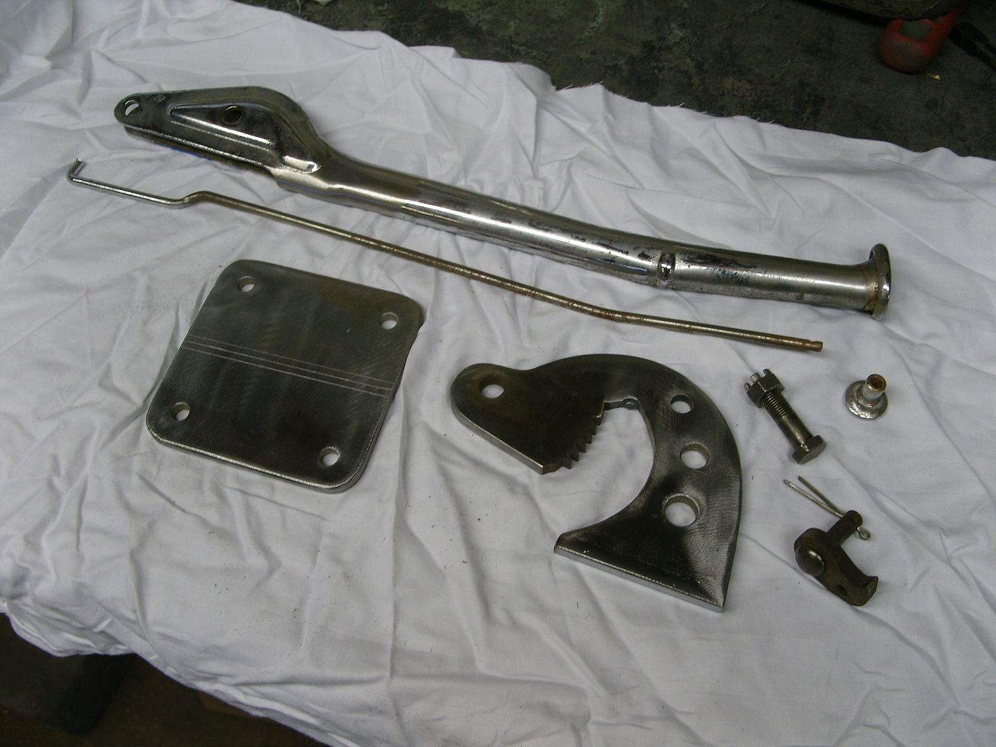
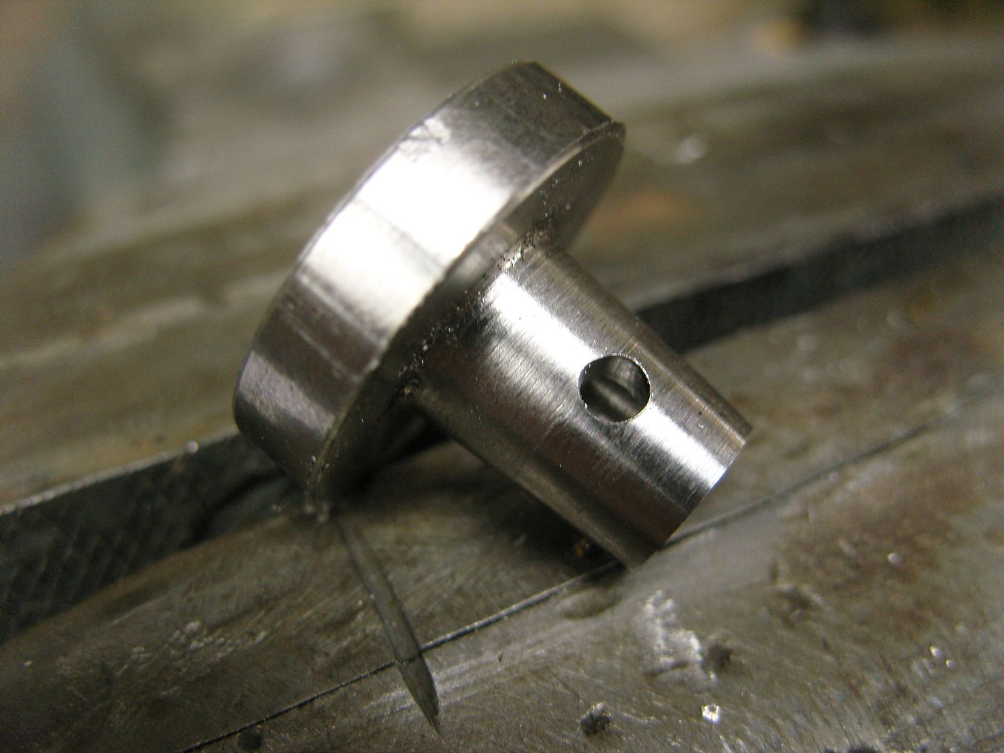
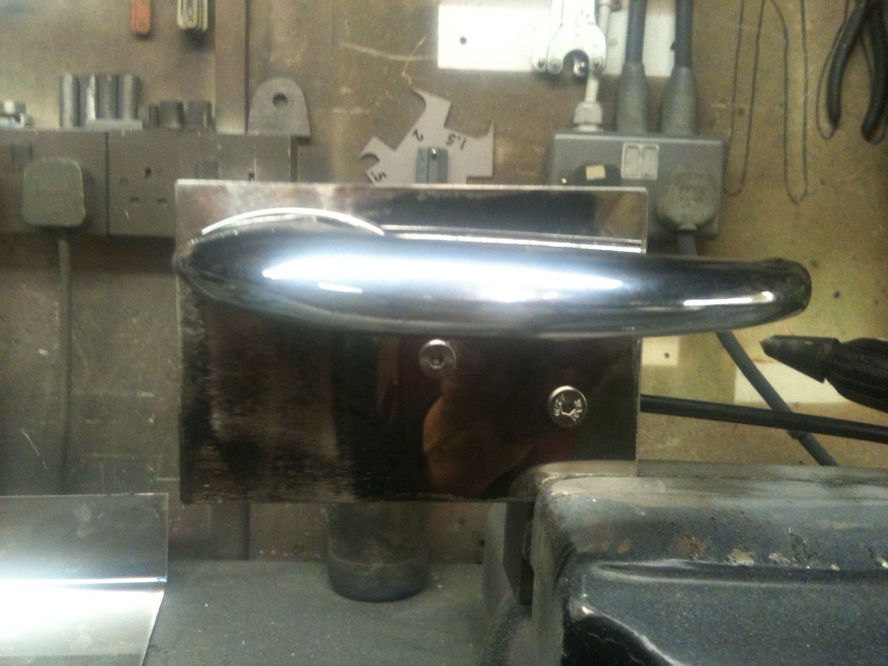
Been looking around for door handles & window winders but couldn't find anything suitable so decided to make some, found some offcuts of 1" round stainless and a few bits of 3/16" stainless plate, These are similair to my 26T handles but more simple which fits in with the car.
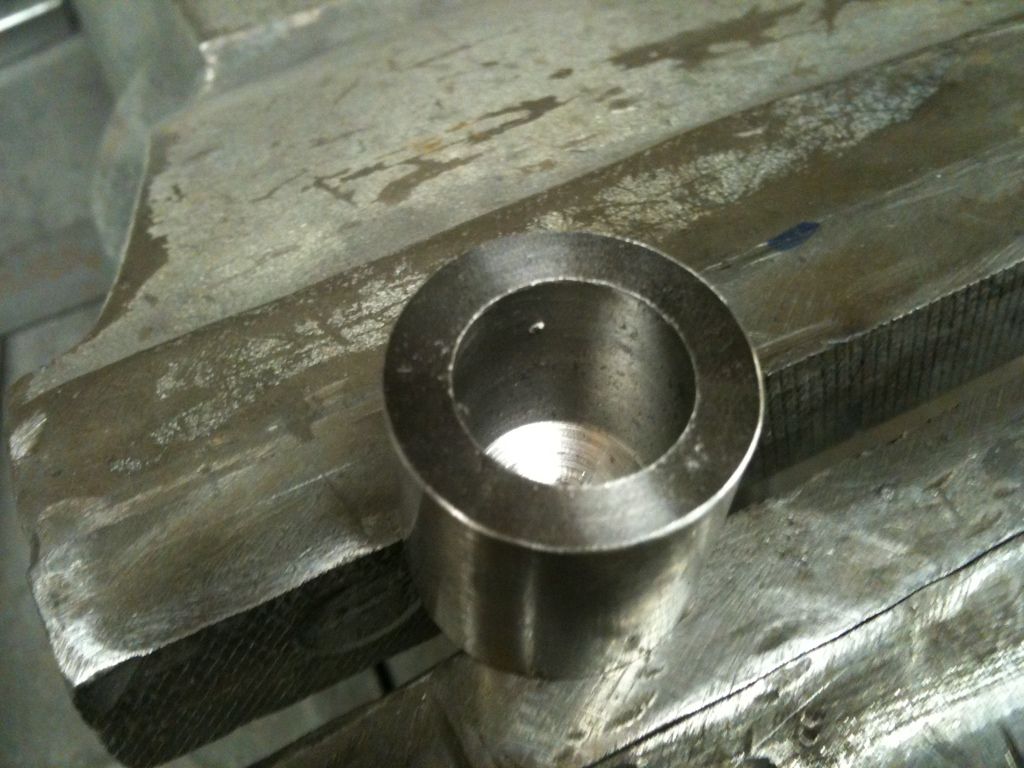
First job was to turn up and bore out the 1" bar for the handle bases.
Next i needed to get the hole square to match the square shafts, a bit of 2mm stainless sheet was cut up and folded round a bit of square bar, then the joint was welded.
Next the square tube was pressed into the bored out are of the handle bases.
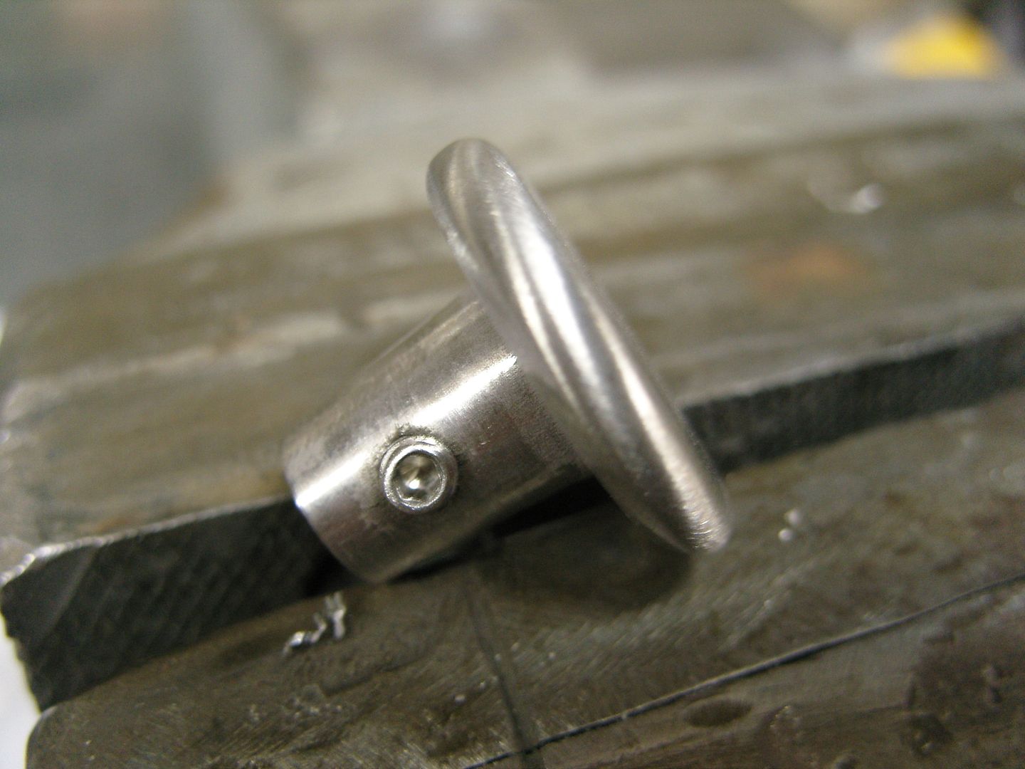
Next job was to weld them in. Then they went back in the lathe to be faced off.
Heres the handles finished, they just need polishing to finish.
:cheers:
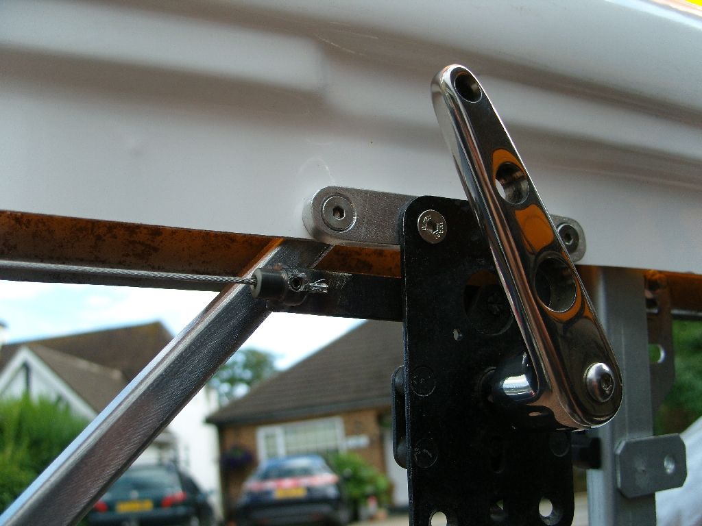
Finally picked up a pair of trail plates for the handles/locks, big thank you to my good friend Paul Nichols (morris460) who donated them.
First job was to make up some solderless nipples as i'm using stainless cables to link them to the locks, I welded a nipple to each trail plate arm to accept the cable.
The lock arm already has an arm ready to accept the cable nipple.
It all works real nice.
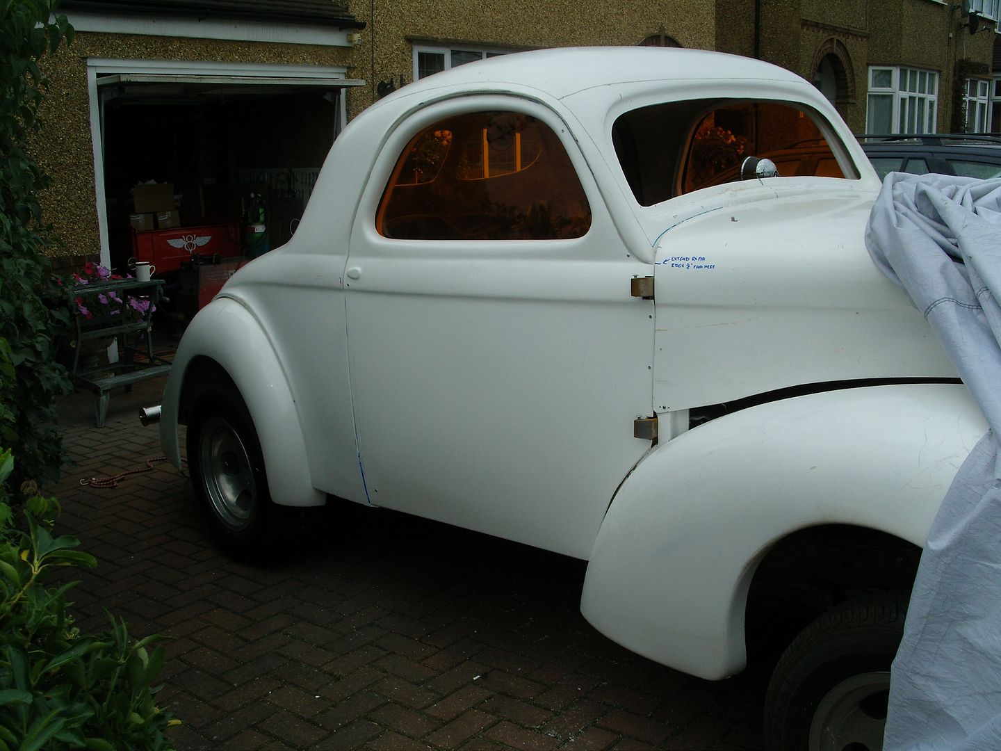
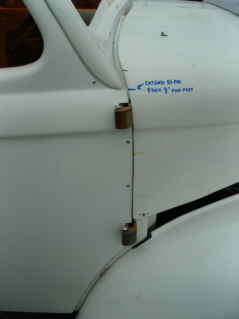
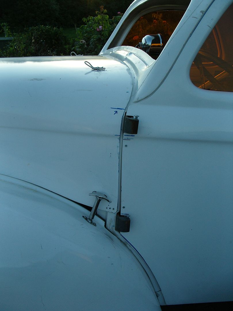
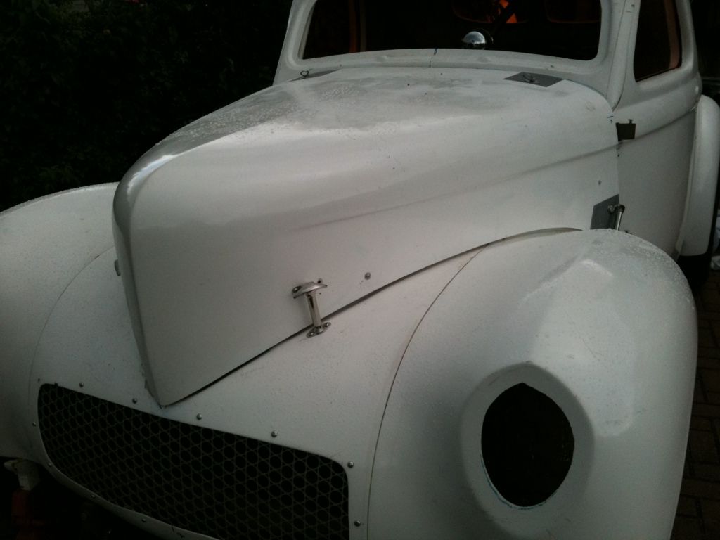
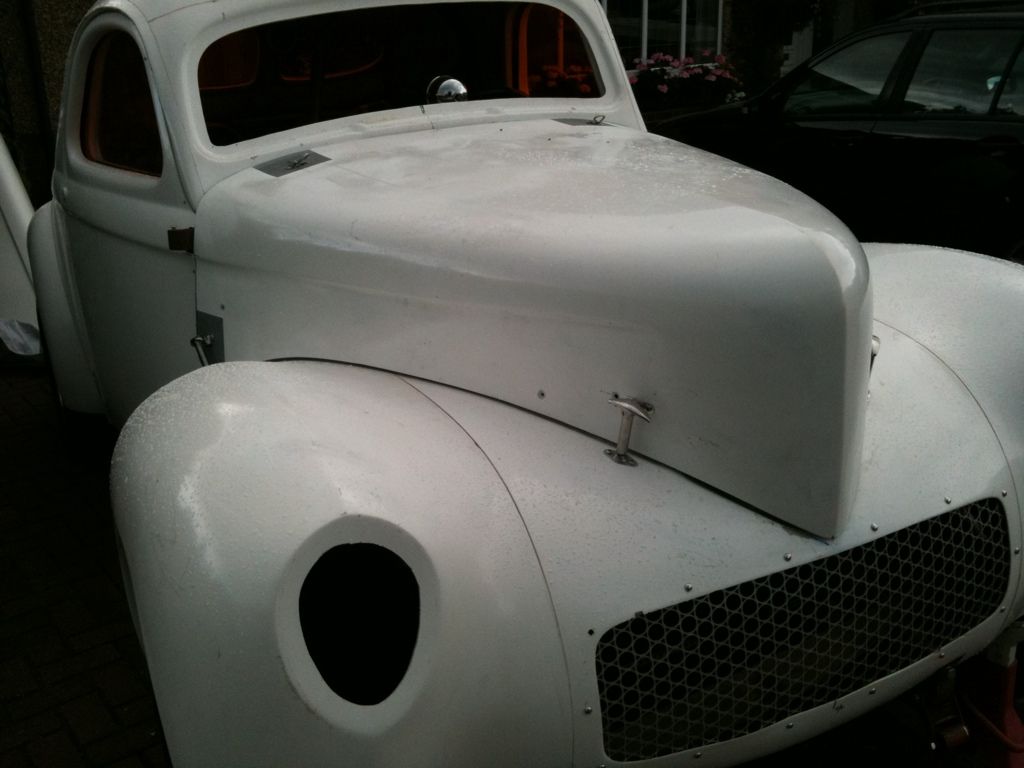
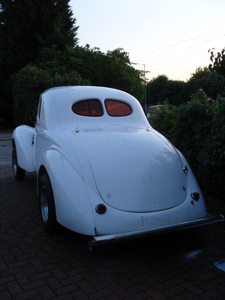
Now the doors are virtually there i started on the hood, Its taken a couple of evenings to get right but i found the best way was to get the hood lined up with the beltline and then adjust the fenders to suit,
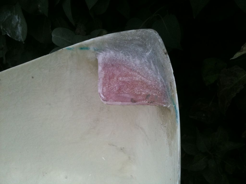
It fits pretty well but being a single skin it tends to be a bit floppy so needed a little bracing here and there, first i attended to the rear side corners that stick out a little, it needed a simple brace on the curve to keep it in the right shape.
A bit of measuring and a piece of tape to keep the sides constant and work progressed.
A piece of 3/8" ply was cut as a stiffner and the area keyed up, the ply is held in place with a few blobs of body filler. Then matting applied, no picture of the matting going on as my fingers were a bit sticky.
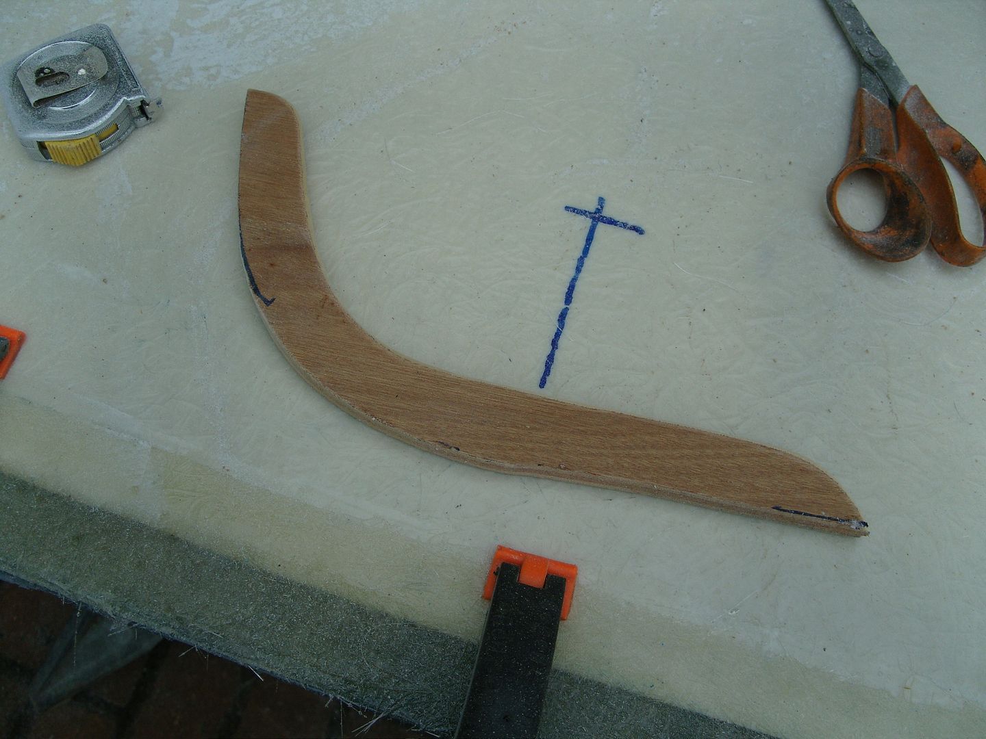
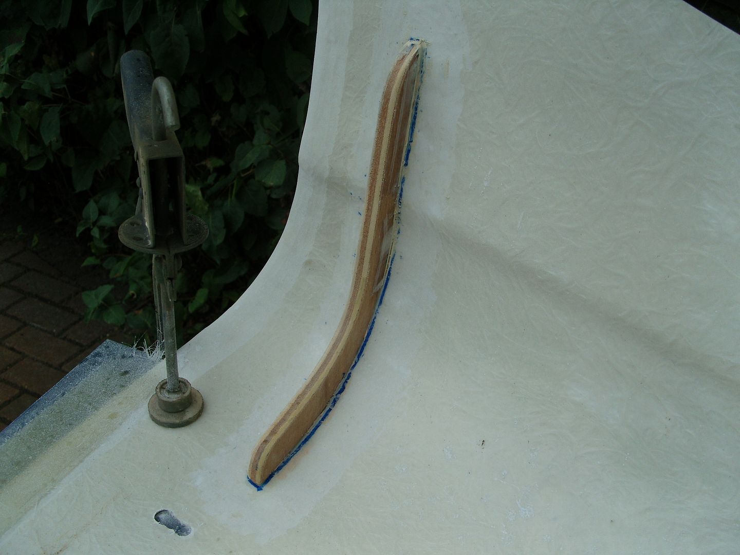
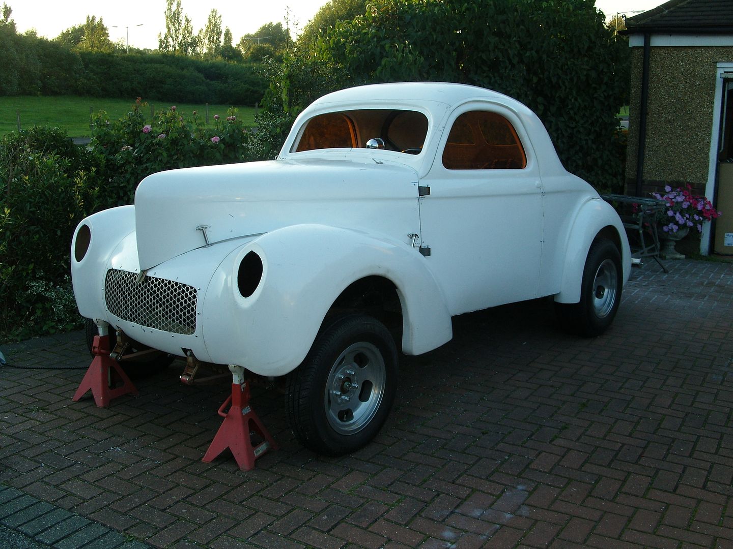
Here its fitted back on the car, 32 hood hold downs like they used back in the 60's, apart from a bit of blending and fettling of the gaps its virtually there. There will be no tight door gaps here as Willys were never known for their great panel fitment, don't want it too perfect otherwise it will look like a glass car
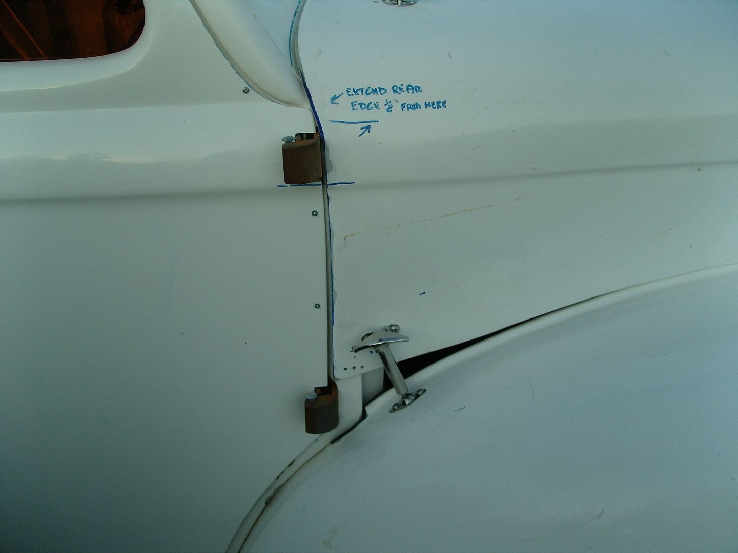
Bonded in a small glass bracket for a pin to keep the hood aligned.
First job was to turn up and bore out the 1" bar for the handle bases.
Next i needed to get the hole square to match the square shafts, a bit of 2mm stainless sheet was cut up and folded round a bit of square bar, then the joint was welded.
Next the square tube was pressed into the bored out are of the handle bases.
Next job was to weld them in. Then they went back in the lathe to be faced off.
Heres the handles finished, they just need polishing to finish.
:cheers:
Finally picked up a pair of trail plates for the handles/locks, big thank you to my good friend Paul Nichols (morris460) who donated them.
First job was to make up some solderless nipples as i'm using stainless cables to link them to the locks, I welded a nipple to each trail plate arm to accept the cable.
The lock arm already has an arm ready to accept the cable nipple.
It all works real nice.
Now the doors are virtually there i started on the hood, Its taken a couple of evenings to get right but i found the best way was to get the hood lined up with the beltline and then adjust the fenders to suit,
It fits pretty well but being a single skin it tends to be a bit floppy so needed a little bracing here and there, first i attended to the rear side corners that stick out a little, it needed a simple brace on the curve to keep it in the right shape.
A bit of measuring and a piece of tape to keep the sides constant and work progressed.
A piece of 3/8" ply was cut as a stiffner and the area keyed up, the ply is held in place with a few blobs of body filler. Then matting applied, no picture of the matting going on as my fingers were a bit sticky.
Here its fitted back on the car, 32 hood hold downs like they used back in the 60's, apart from a bit of blending and fettling of the gaps its virtually there. There will be no tight door gaps here as Willys were never known for their great panel fitment, don't want it too perfect otherwise it will look like a glass car
Bonded in a small glass bracket for a pin to keep the hood aligned.
langy
langys rodshop
- Messages
- 6,095
- Location
- London
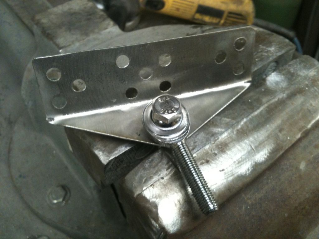
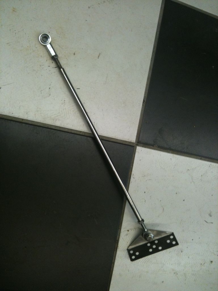
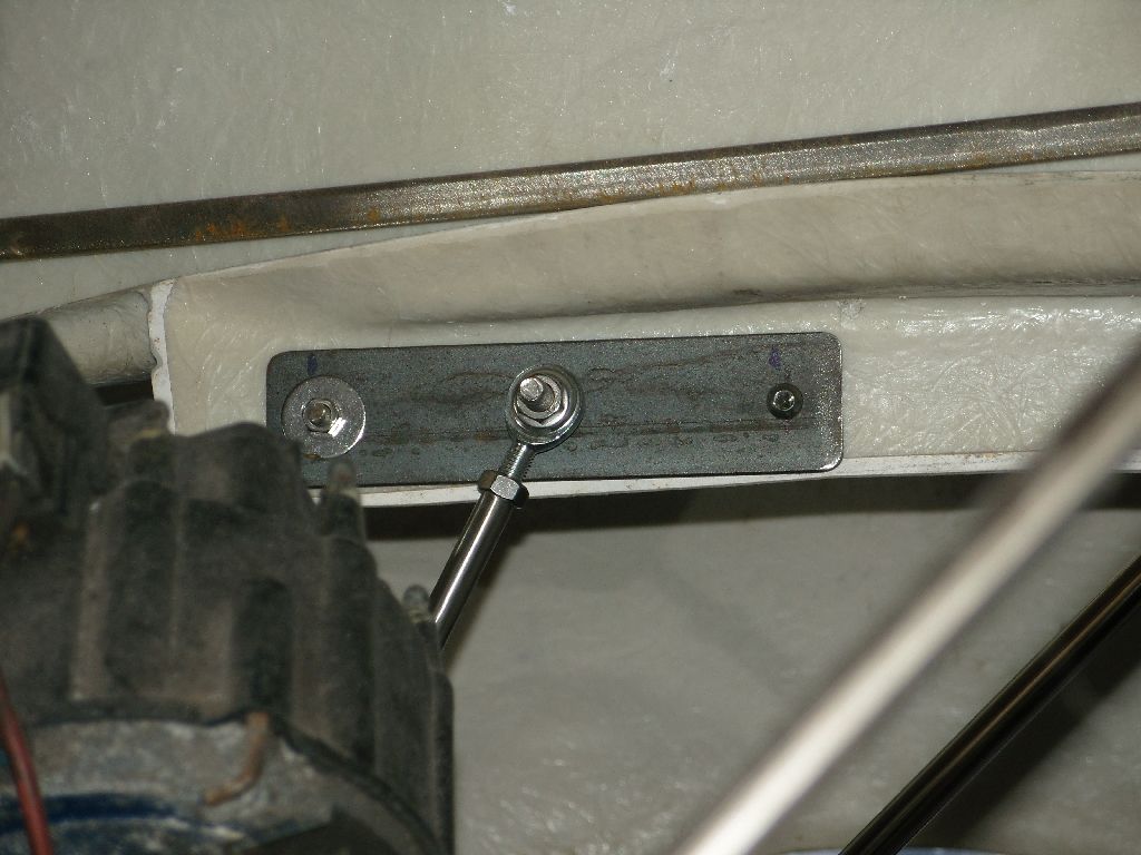
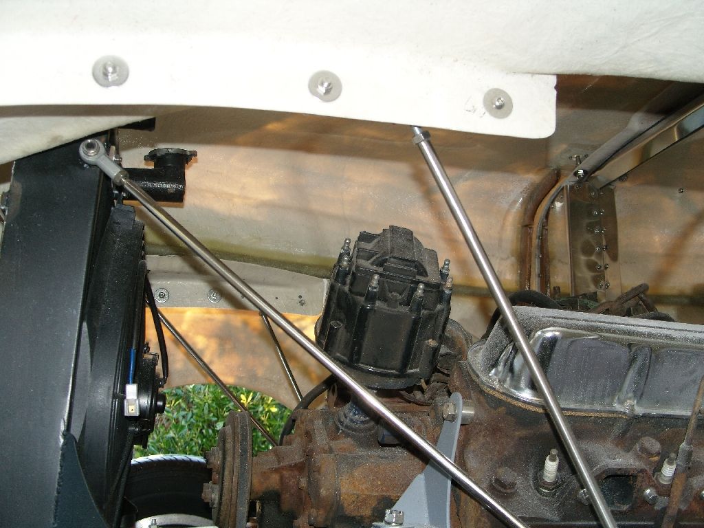
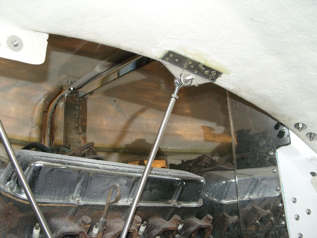
After getting the hood 99% sorted i moved onto the fenders, they needed a bit of support as there is no inner fenders and I don't intend to fit any.
My solution was to add a few adjustable bars to support and adjust the fender to hood clearence.
The bars use 5/16" male & female cheap joints, The tube is 3/8" OD x 14swg wall so i could tap dierectly into it.
The bars pickup on the radiator bar lower mounts.
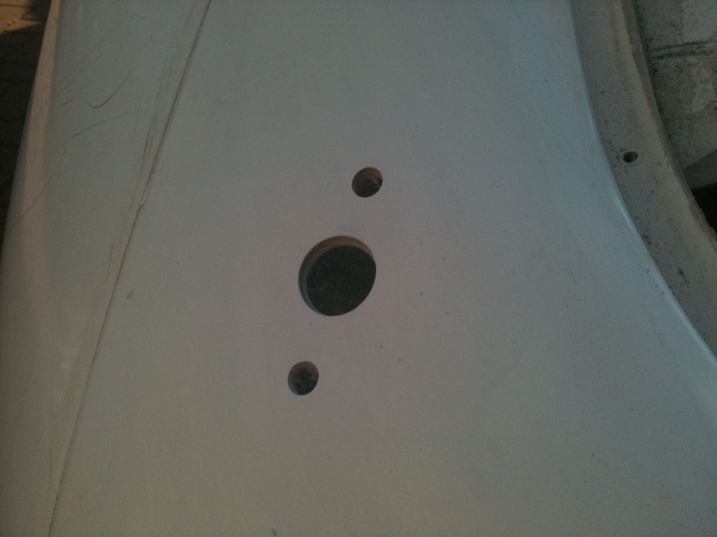
A piece of 2" x 1" wood is a temporary prop. The rear mount is glassed into the fender, it has holes randomly drilled to aid with the bonding.
Sorry this bit is a bit boring but i know there a 3 people who bought bodies from me and it may help them.
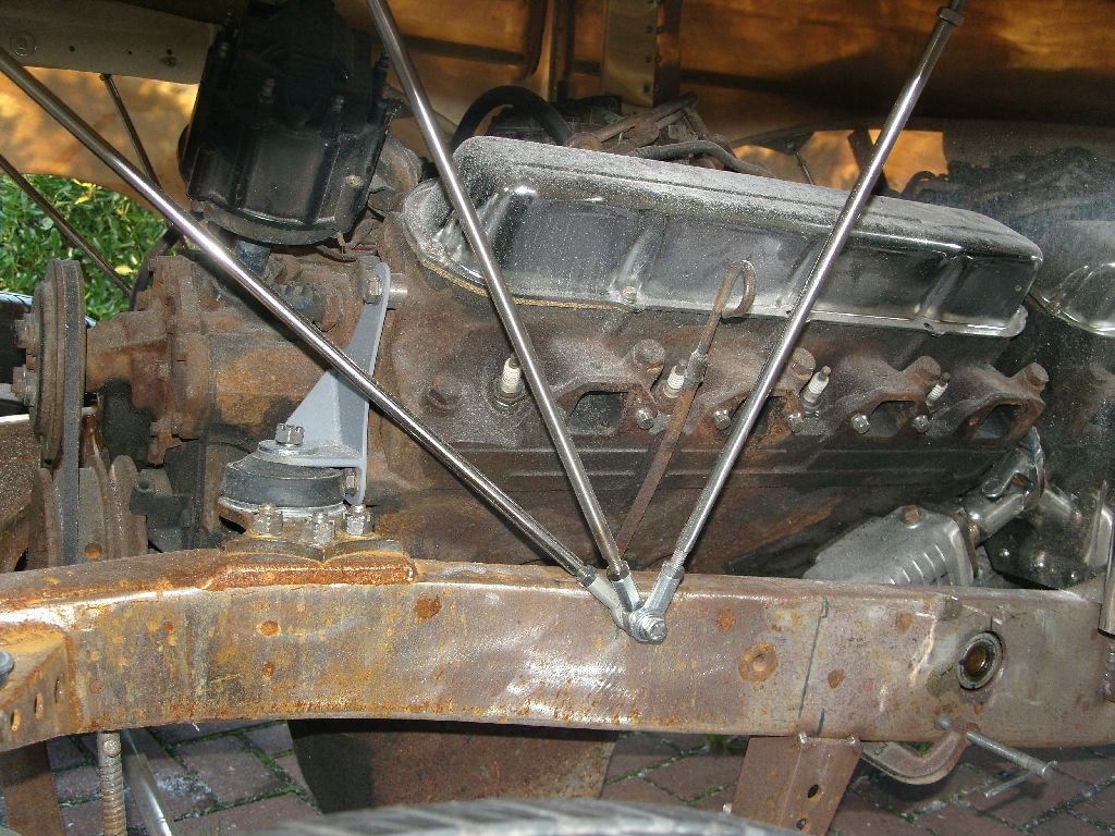
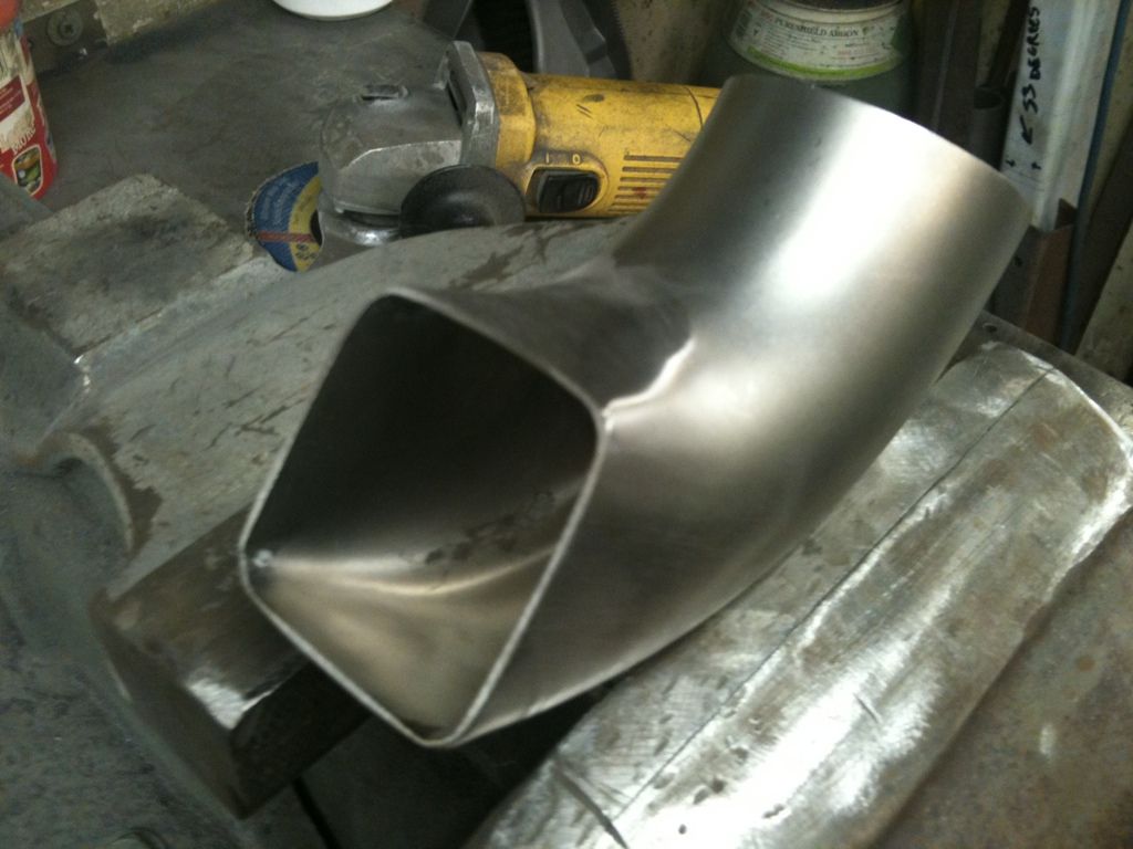
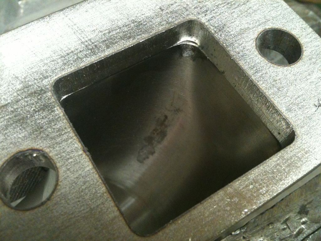
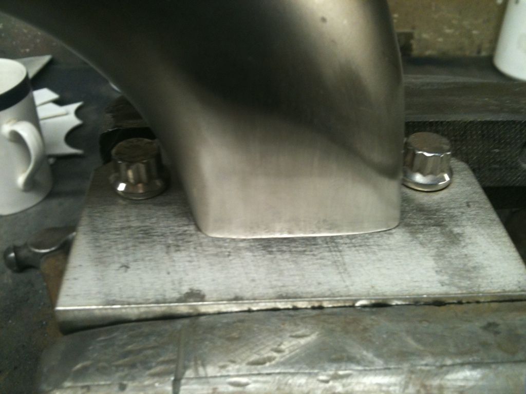
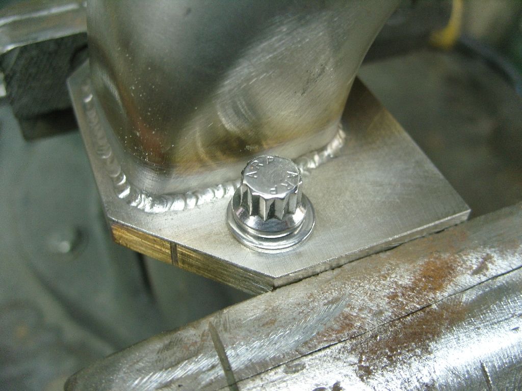
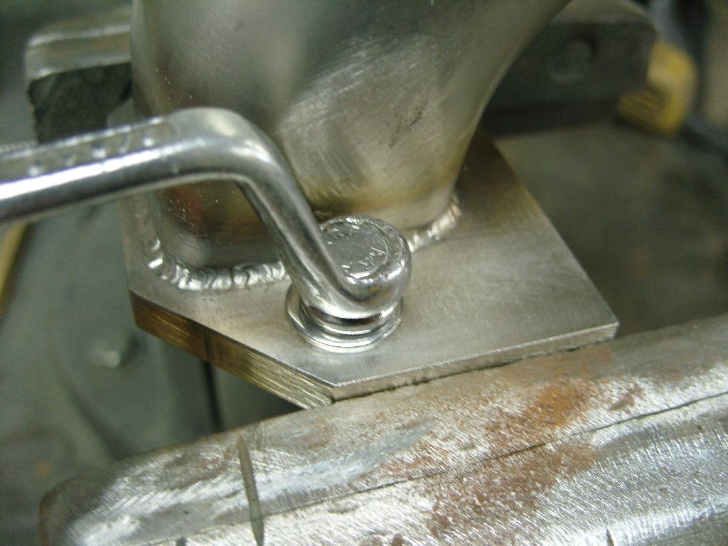
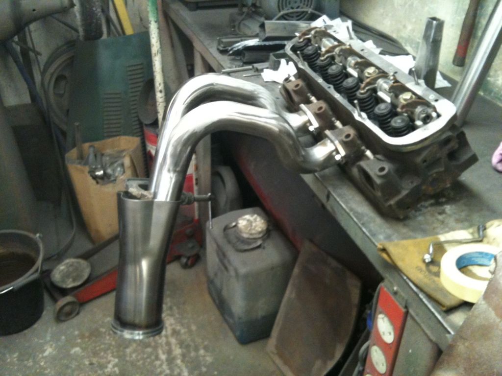
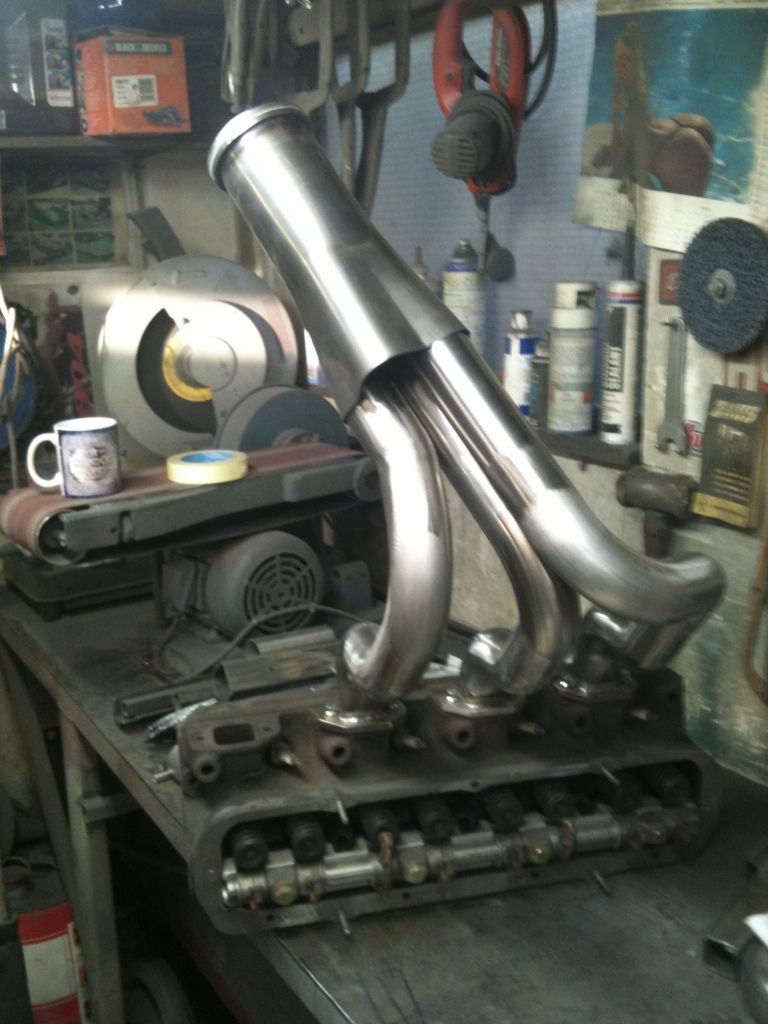
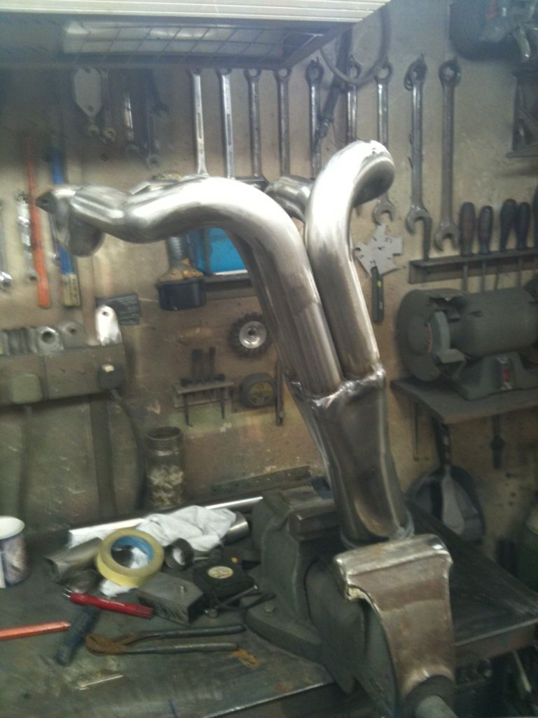
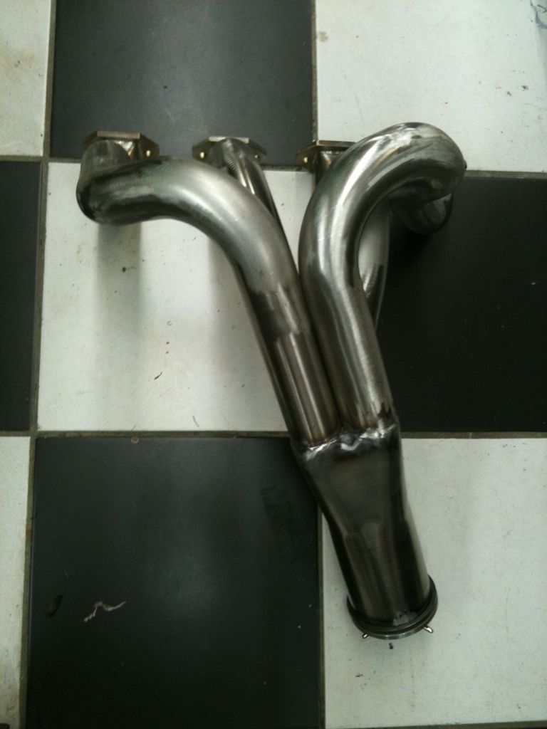
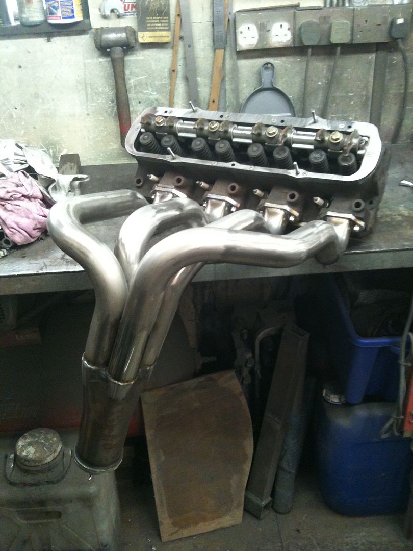
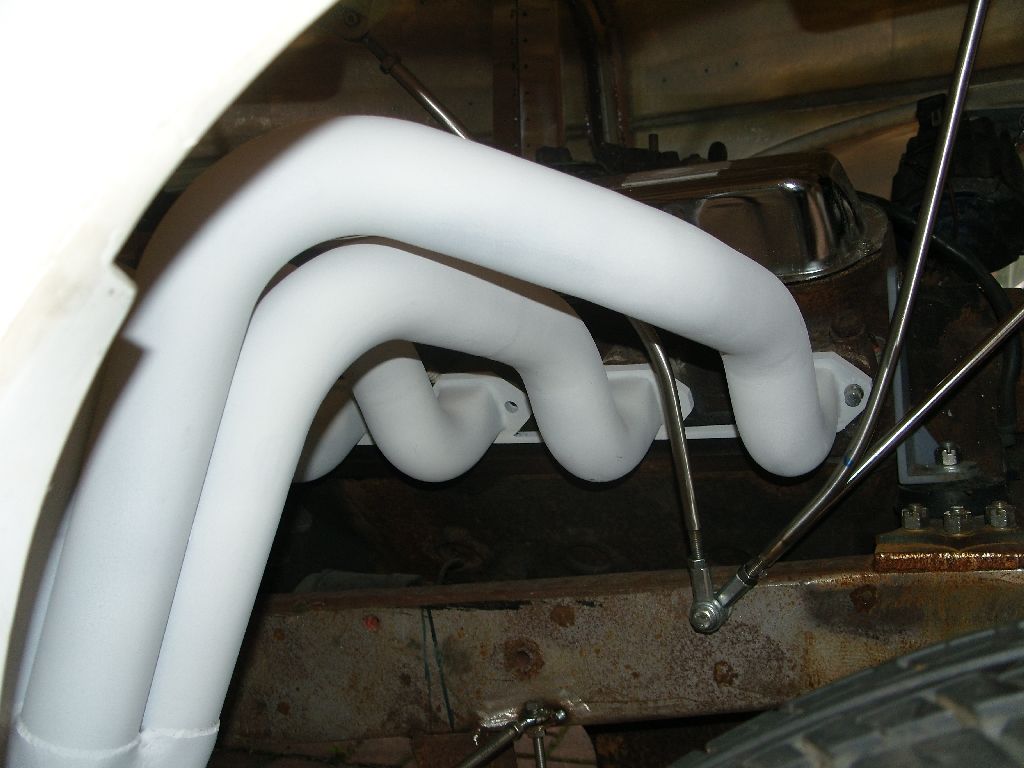
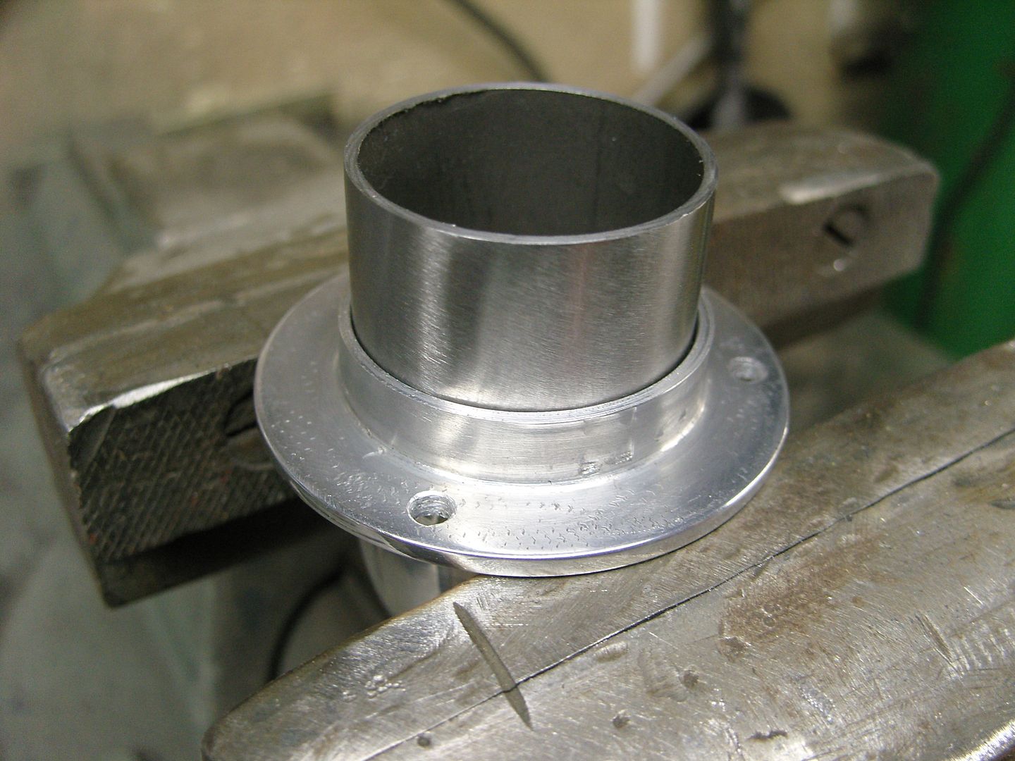
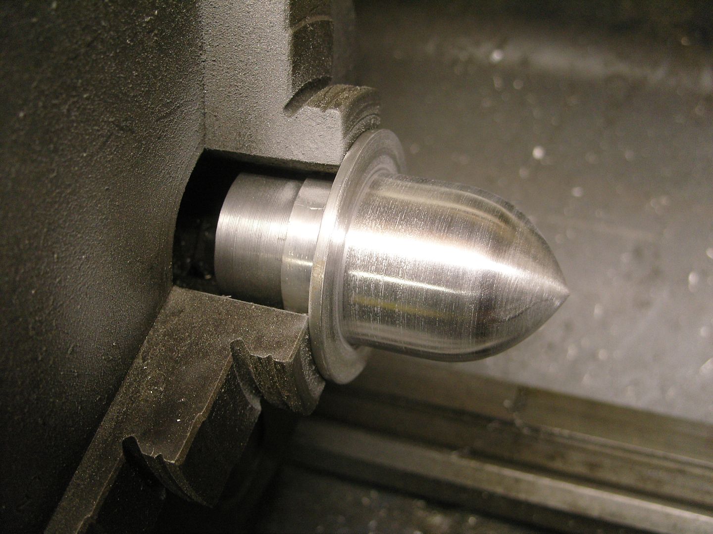
The last couple of evenings have been raining so i carried on in the workshop and started making the headers, The Cadillac is like a Ford and has square primary pipes.
Luckily i still had a tool that i made as an apprentice for making Ford header pipes square 40 years ago, Its just a few bits of 1/4" steel plate welded together in a taper and then the pipe is hammered square, works well even with stainless tube. The primaries are 316L stainless steel 2" OD which is slightly over 1-7/8" ID
My solution was to add a few adjustable bars to support and adjust the fender to hood clearence.
The bars use 5/16" male & female cheap joints, The tube is 3/8" OD x 14swg wall so i could tap dierectly into it.
The bars pickup on the radiator bar lower mounts.
A piece of 2" x 1" wood is a temporary prop. The rear mount is glassed into the fender, it has holes randomly drilled to aid with the bonding.
Sorry this bit is a bit boring but i know there a 3 people who bought bodies from me and it may help them.
The last couple of evenings have been raining so i carried on in the workshop and started making the headers, The Cadillac is like a Ford and has square primary pipes.
Luckily i still had a tool that i made as an apprentice for making Ford header pipes square 40 years ago, Its just a few bits of 1/4" steel plate welded together in a taper and then the pipe is hammered square, works well even with stainless tube. The primaries are 316L stainless steel 2" OD which is slightly over 1-7/8" ID
langy
langys rodshop
- Messages
- 6,095
- Location
- London
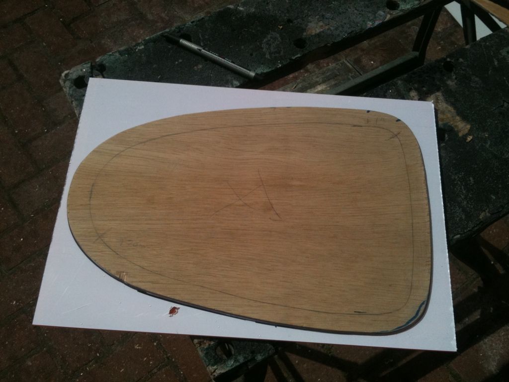
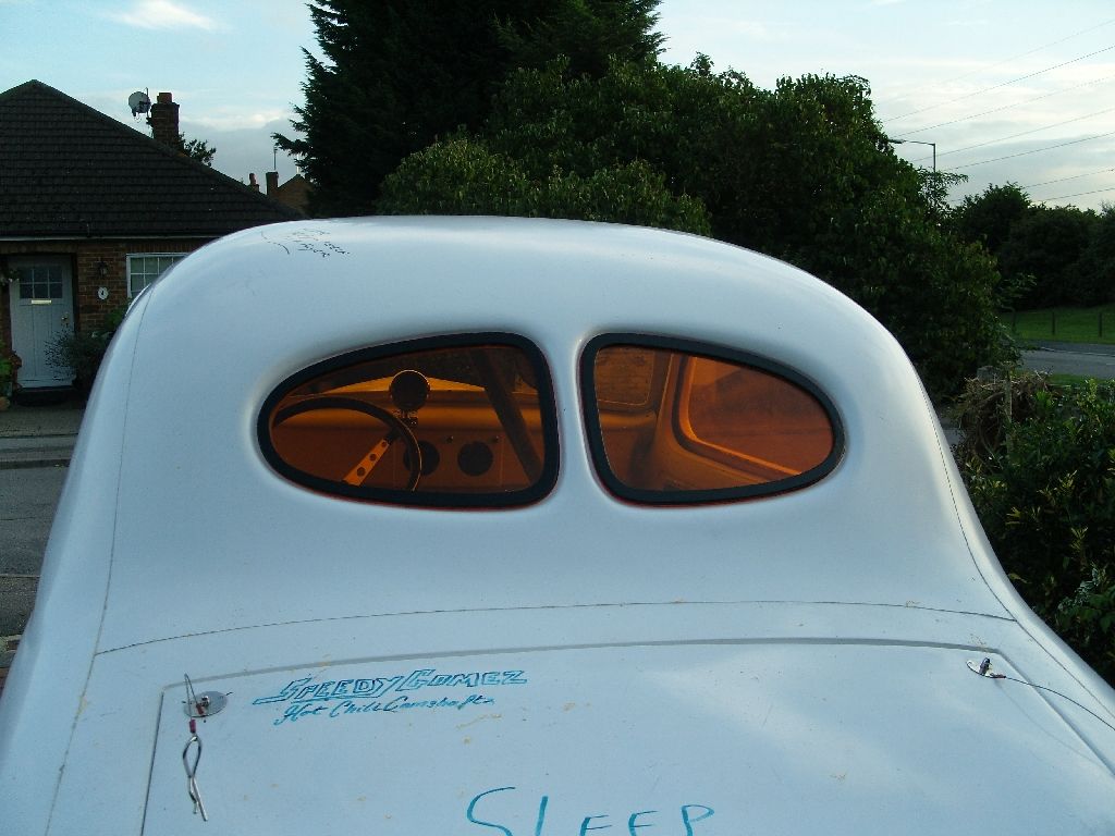
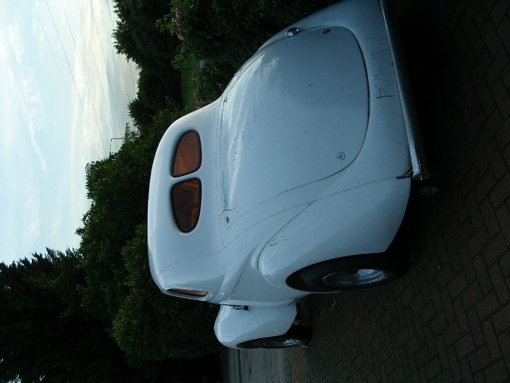
What a weird day today was, an hour of sun then a rain shower and then back to sun again, been like that all day, anyway during the dry patches my trusty helper Gomez came over to assist in sorting the rear windows as I needed 3 hands.
First job was to make a template
Then the shape was transferred to the acrylic sheet and marked
This is Gomez being humerous, little things please little minds !!!
Next the holes were marked for the 3/16" button head screws, also the inner was marked & cut out.
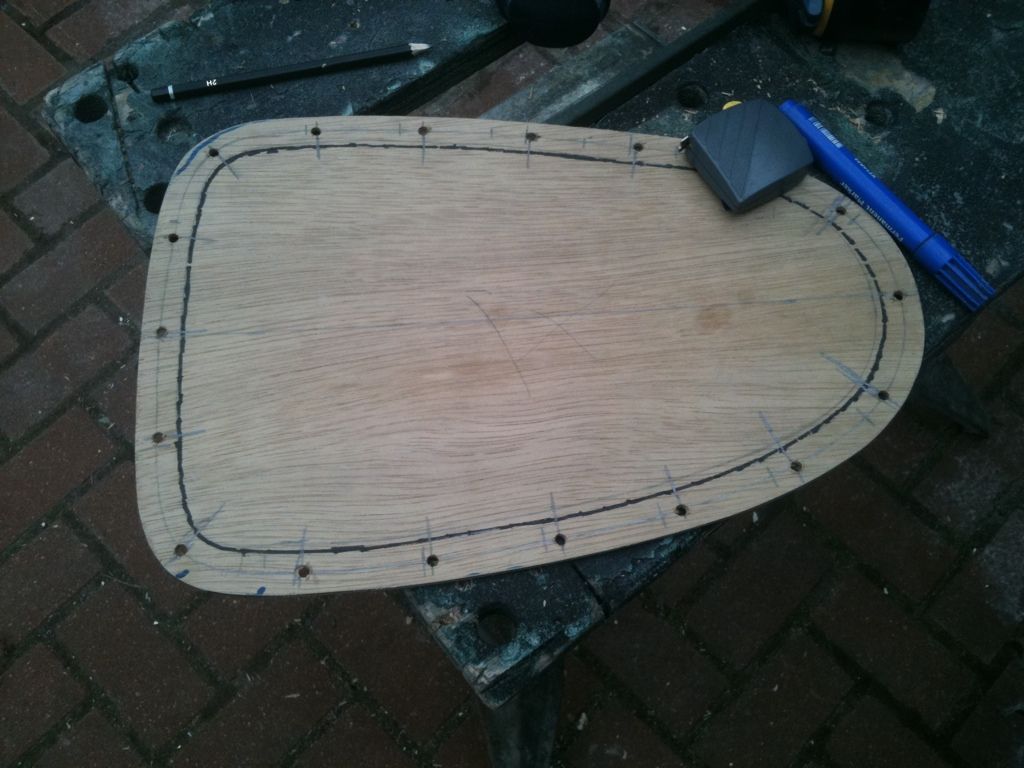
A quick check of the fit, all good.
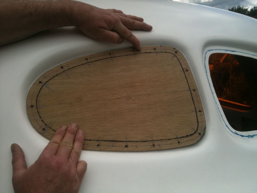
The template was clamped to the body and the holes drilled.
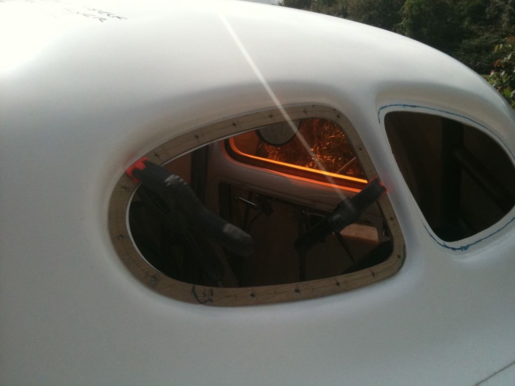
Next the holes were transferred to the acrylic.
Next the windows were bolted in. I was going to paint a black border around the window but i now have a better idea that will look like they are in rubber, stay tuned.
The door & window handles are now polished.
Also the hood is finally gapped, I think i have it right at last but may make the gap slightly bigger when i do the body work as i think its still a little tight to look authentic. Maybe someone with a steel Willys will be able to confirm the gap width ?
Been playing with ideas for a black border around the windows.
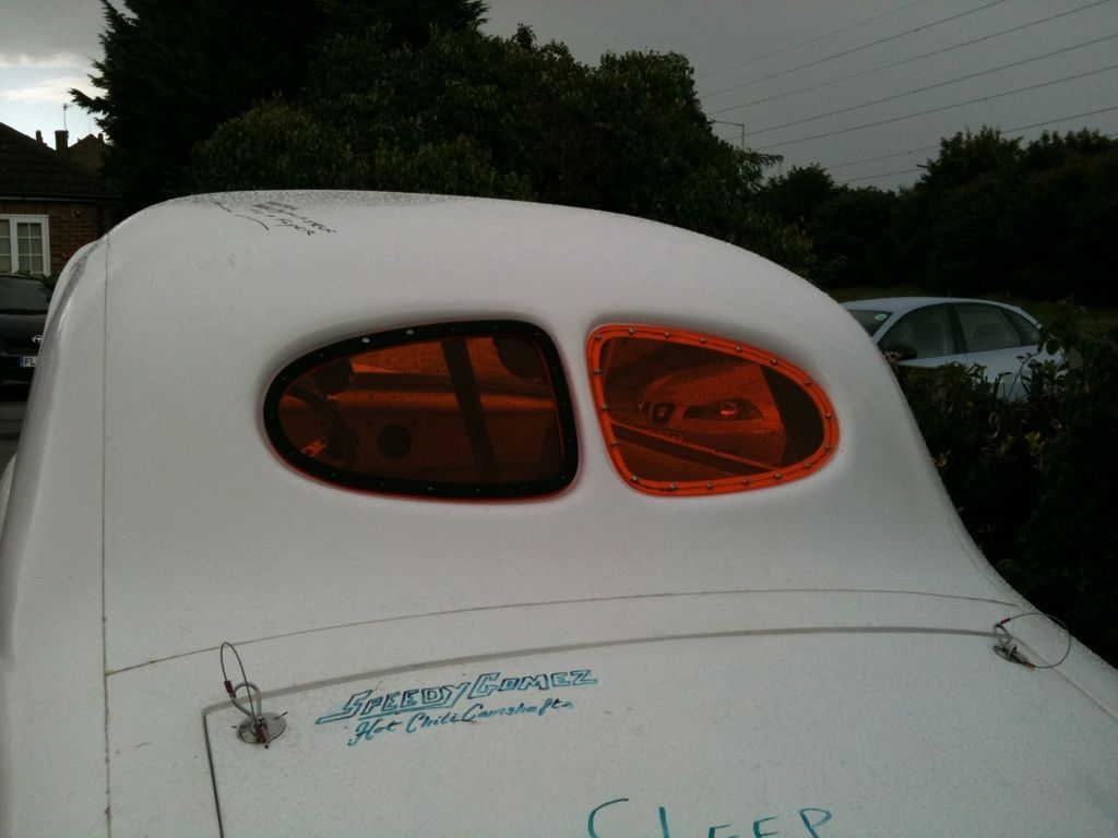
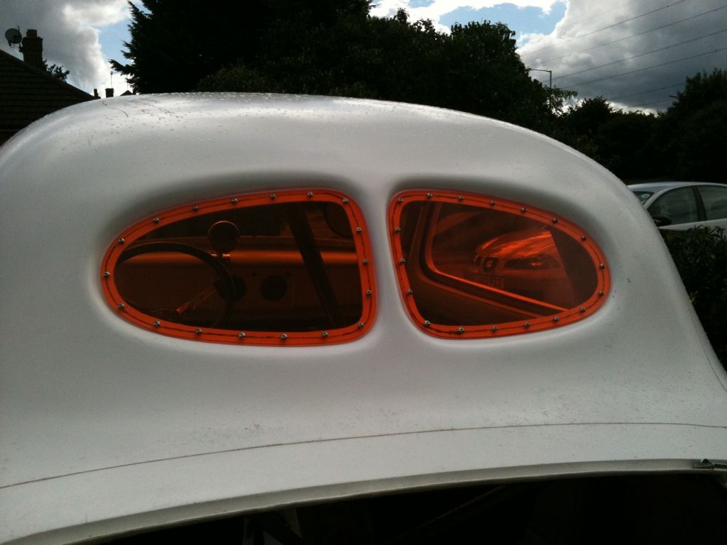
Last night i made up some trims for the rear windows to give the appearence of rubber trim, Looks much better.
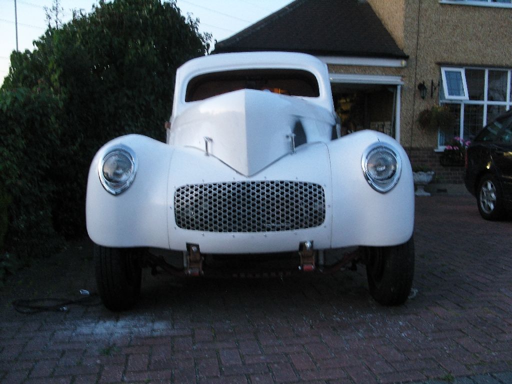
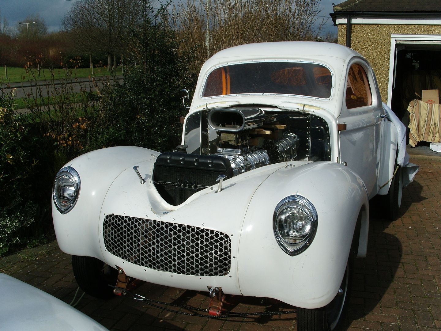
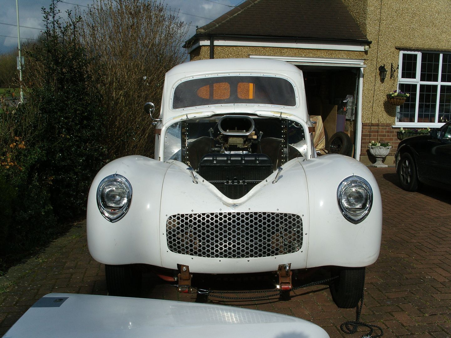
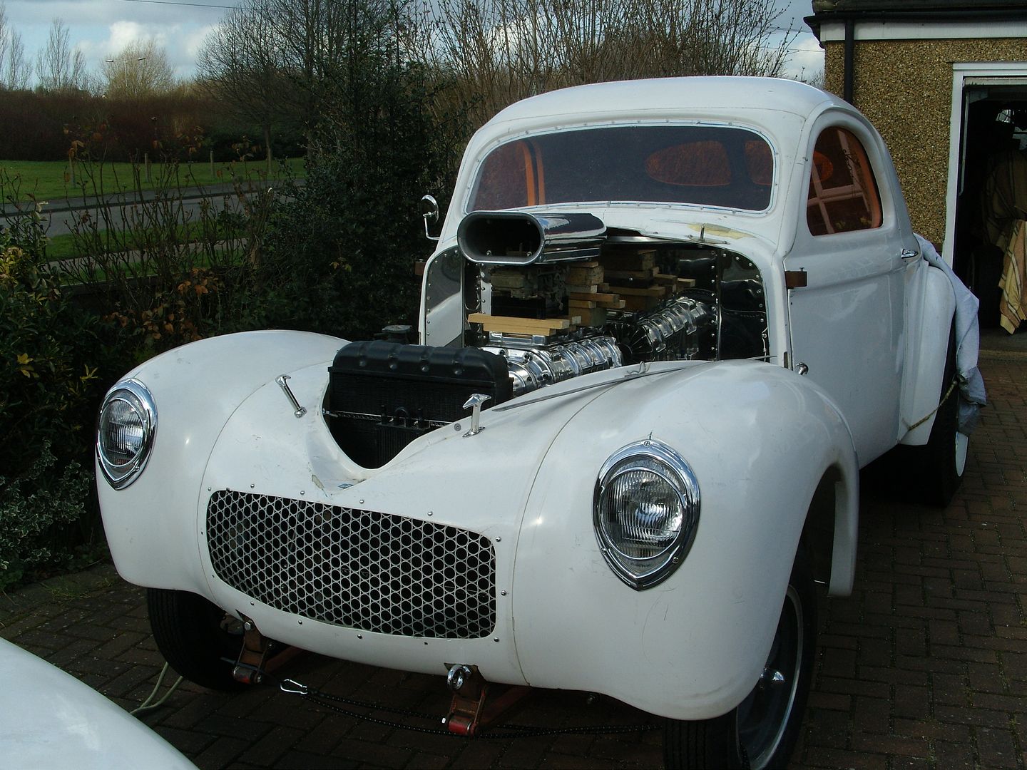
Well after getting over the jetlag i found a couple of hours today so decided to get my headlights/taillights fitted to give the car a face !!!
First job was to cutout the supplied template to find it wasn't as close as it first appeared to be
Any way i used it in the end but moved some of the holes around.
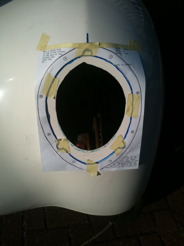
Next the bowl/reflector was trial fitted, these fit from behind so the back side of the GRP was sanded smooth for a good fit.

Then the outside bezel/glass was fitted, really makes the car look different and gives it a face.
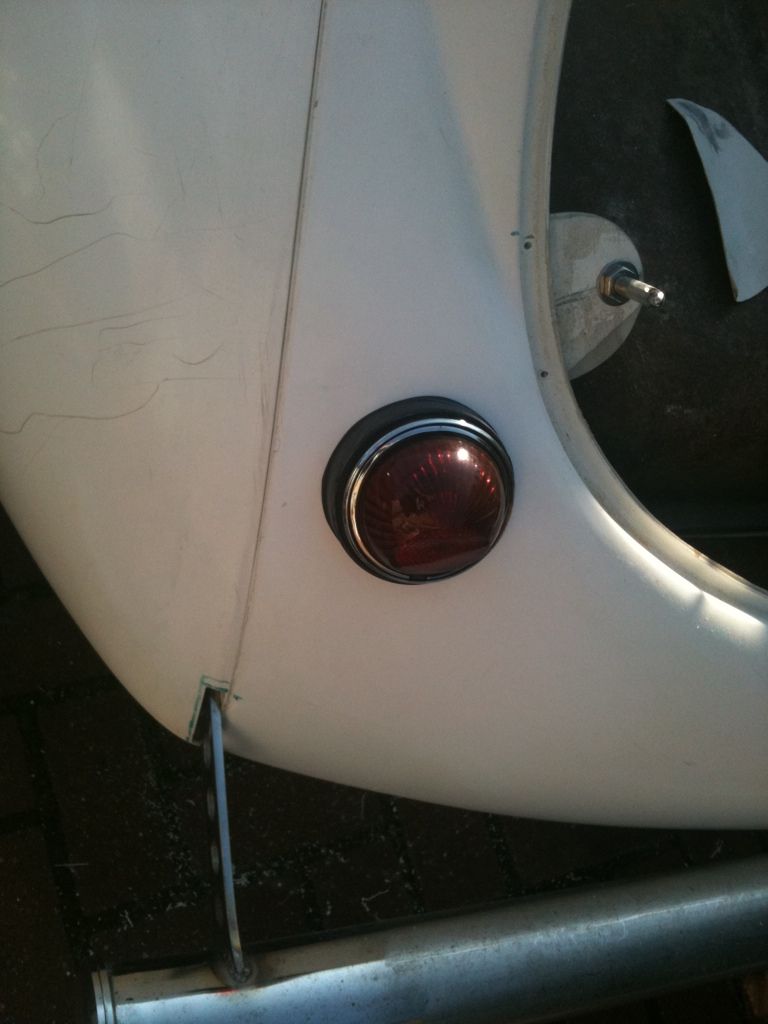
Next i turned to the rear end, A quick phone call to my mate Wayne gave me the dimensions of where they should fit and holes were drilled.
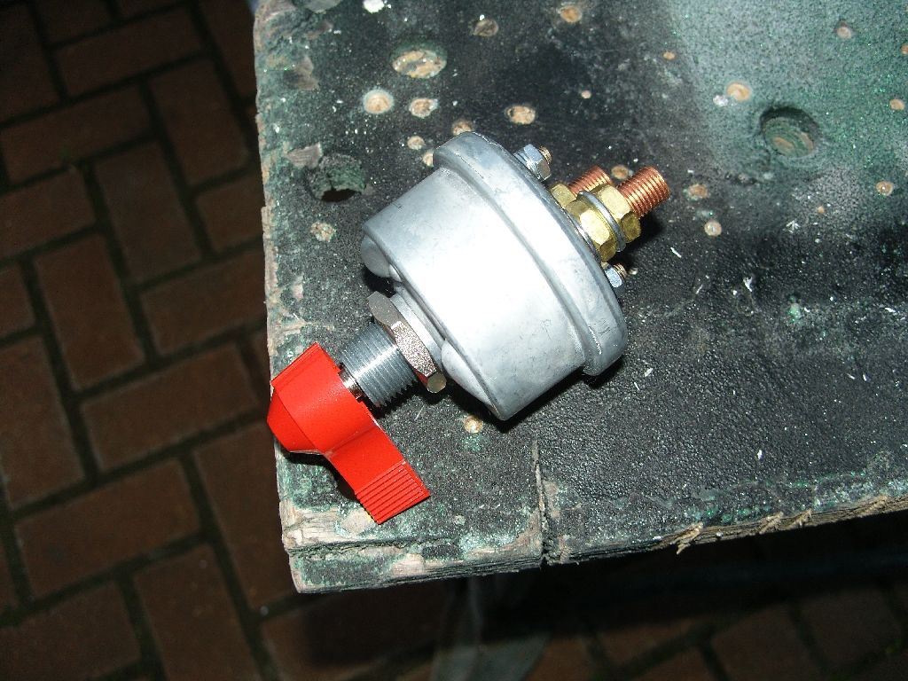
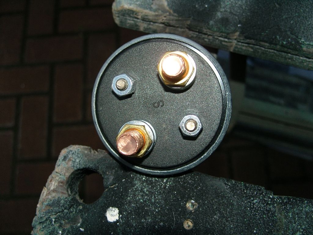
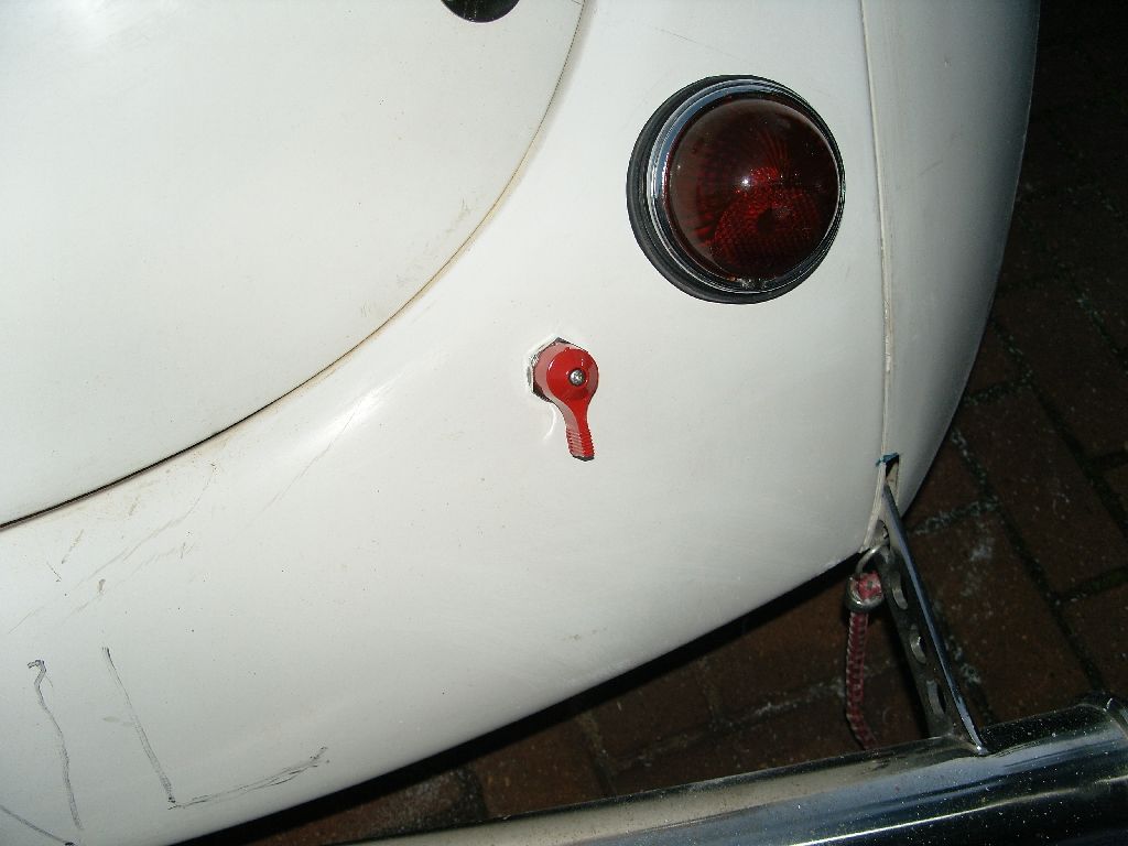
While i was working at the rear i thought i would fit the battery cutoff switch, I went with one with alternator protection from Moroso.
First job was to make a template
Then the shape was transferred to the acrylic sheet and marked
This is Gomez being humerous, little things please little minds !!!
Next the holes were marked for the 3/16" button head screws, also the inner was marked & cut out.
A quick check of the fit, all good.
The template was clamped to the body and the holes drilled.
Next the holes were transferred to the acrylic.
Next the windows were bolted in. I was going to paint a black border around the window but i now have a better idea that will look like they are in rubber, stay tuned.
The door & window handles are now polished.
Also the hood is finally gapped, I think i have it right at last but may make the gap slightly bigger when i do the body work as i think its still a little tight to look authentic. Maybe someone with a steel Willys will be able to confirm the gap width ?
Been playing with ideas for a black border around the windows.
Last night i made up some trims for the rear windows to give the appearence of rubber trim, Looks much better.
Well after getting over the jetlag i found a couple of hours today so decided to get my headlights/taillights fitted to give the car a face !!!
First job was to cutout the supplied template to find it wasn't as close as it first appeared to be
Any way i used it in the end but moved some of the holes around.
Next the bowl/reflector was trial fitted, these fit from behind so the back side of the GRP was sanded smooth for a good fit.
Then the outside bezel/glass was fitted, really makes the car look different and gives it a face.
Next i turned to the rear end, A quick phone call to my mate Wayne gave me the dimensions of where they should fit and holes were drilled.
While i was working at the rear i thought i would fit the battery cutoff switch, I went with one with alternator protection from Moroso.
langy
langys rodshop
- Messages
- 6,095
- Location
- London
Well not much progress today due to getting up a bit late  ain't jetlag a wonderful thing
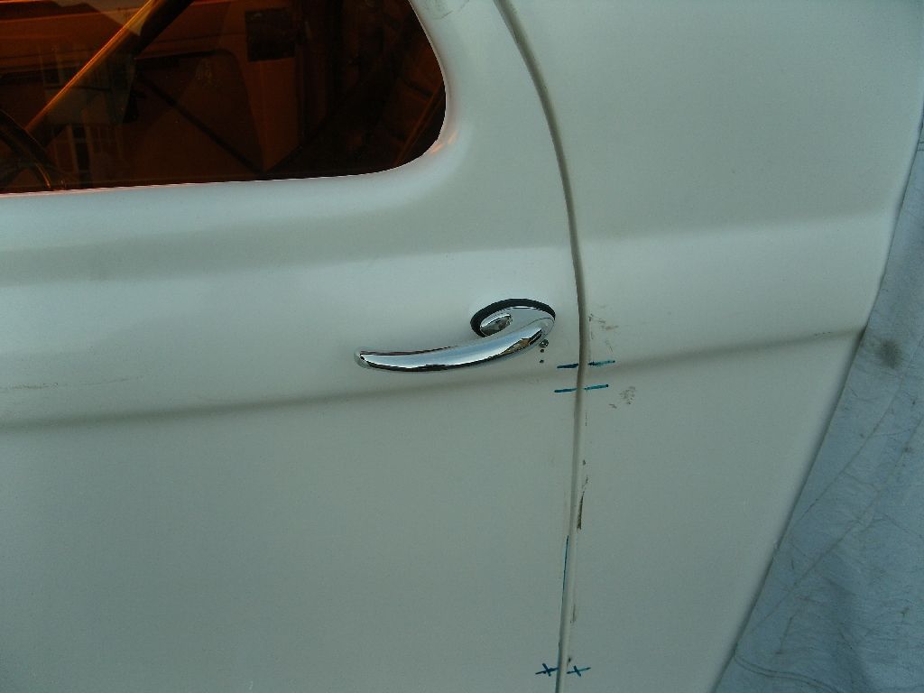
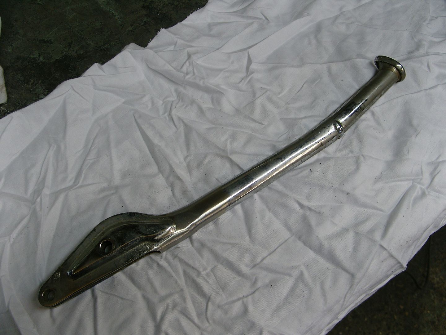
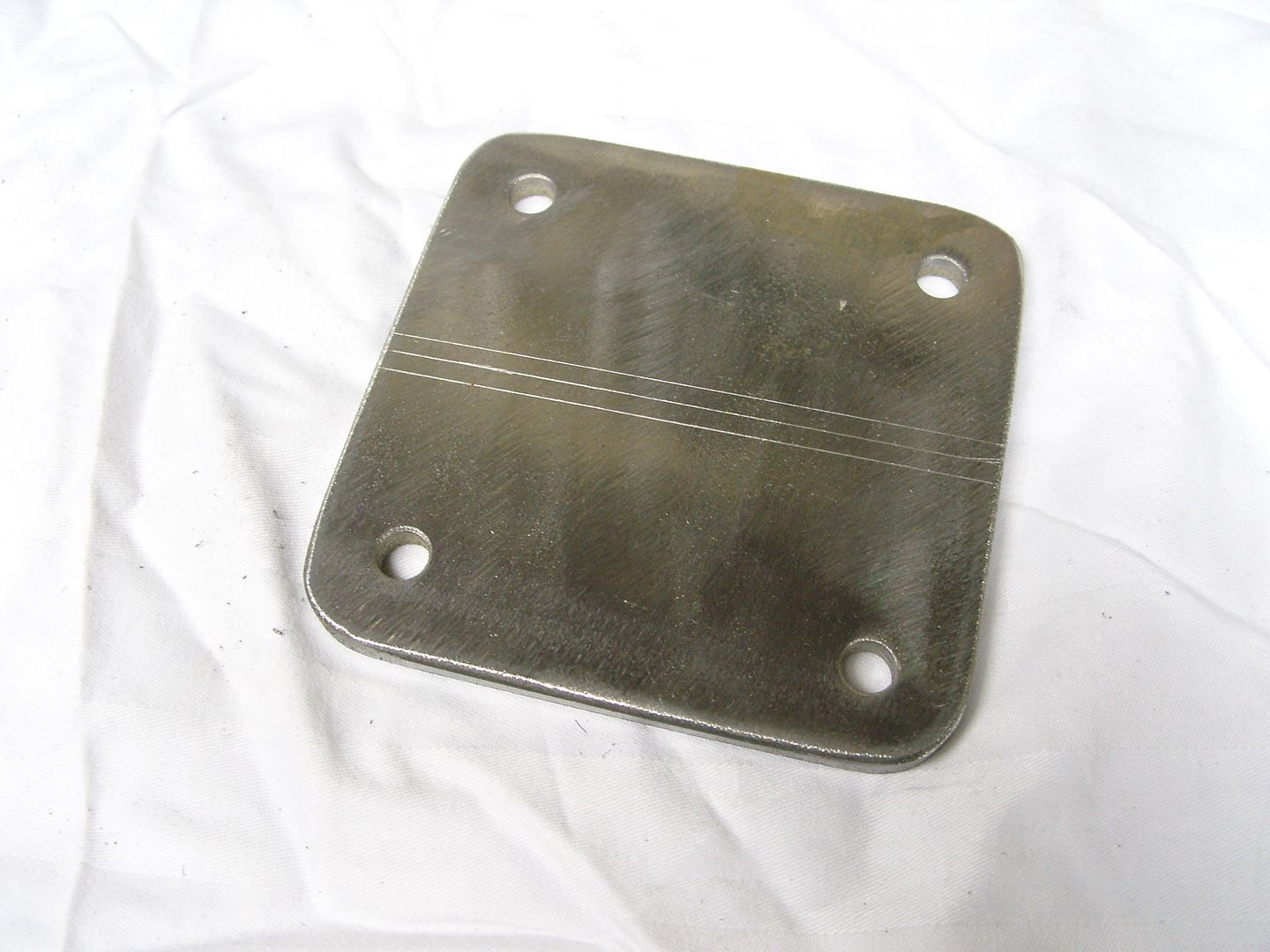
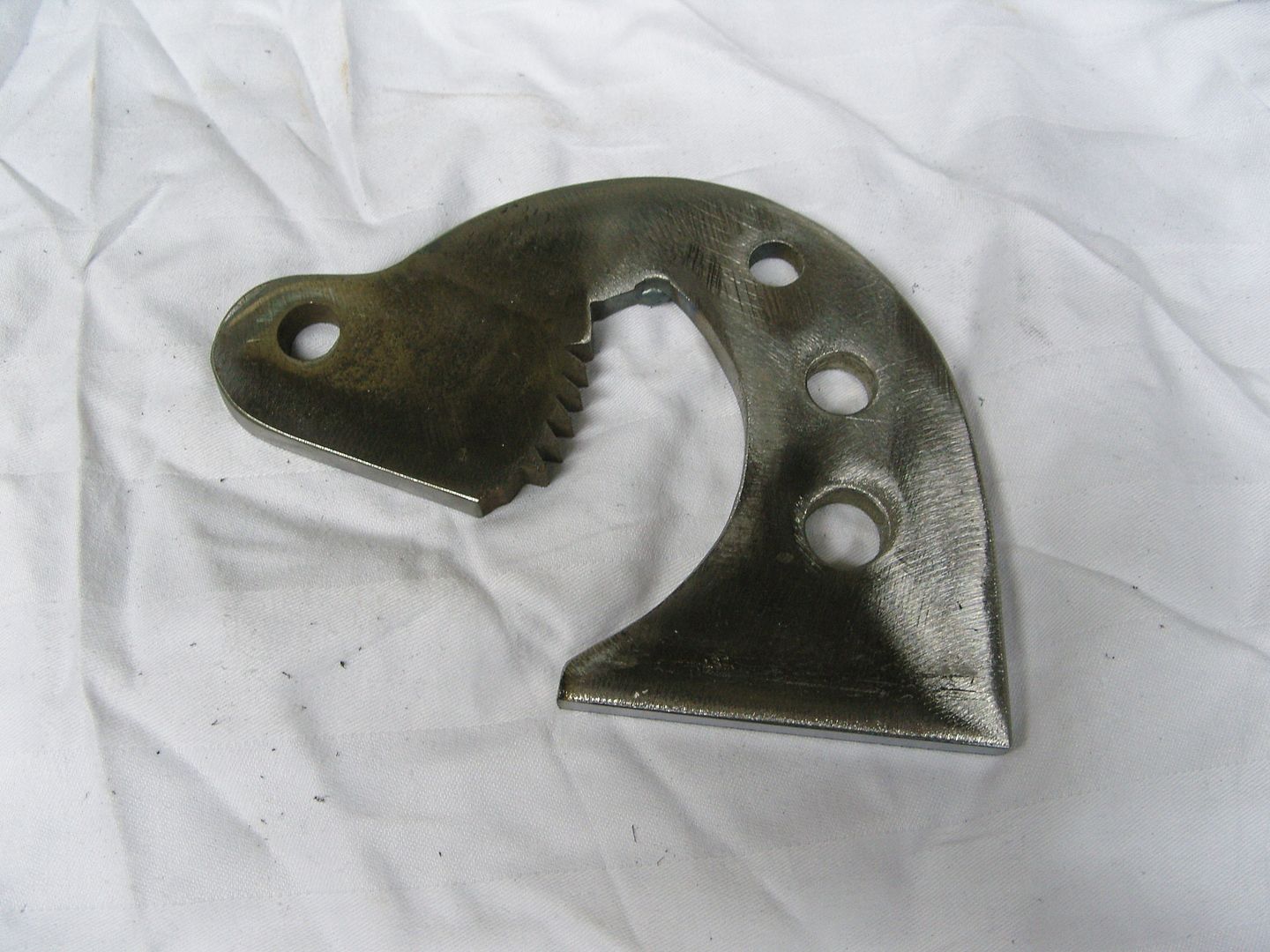
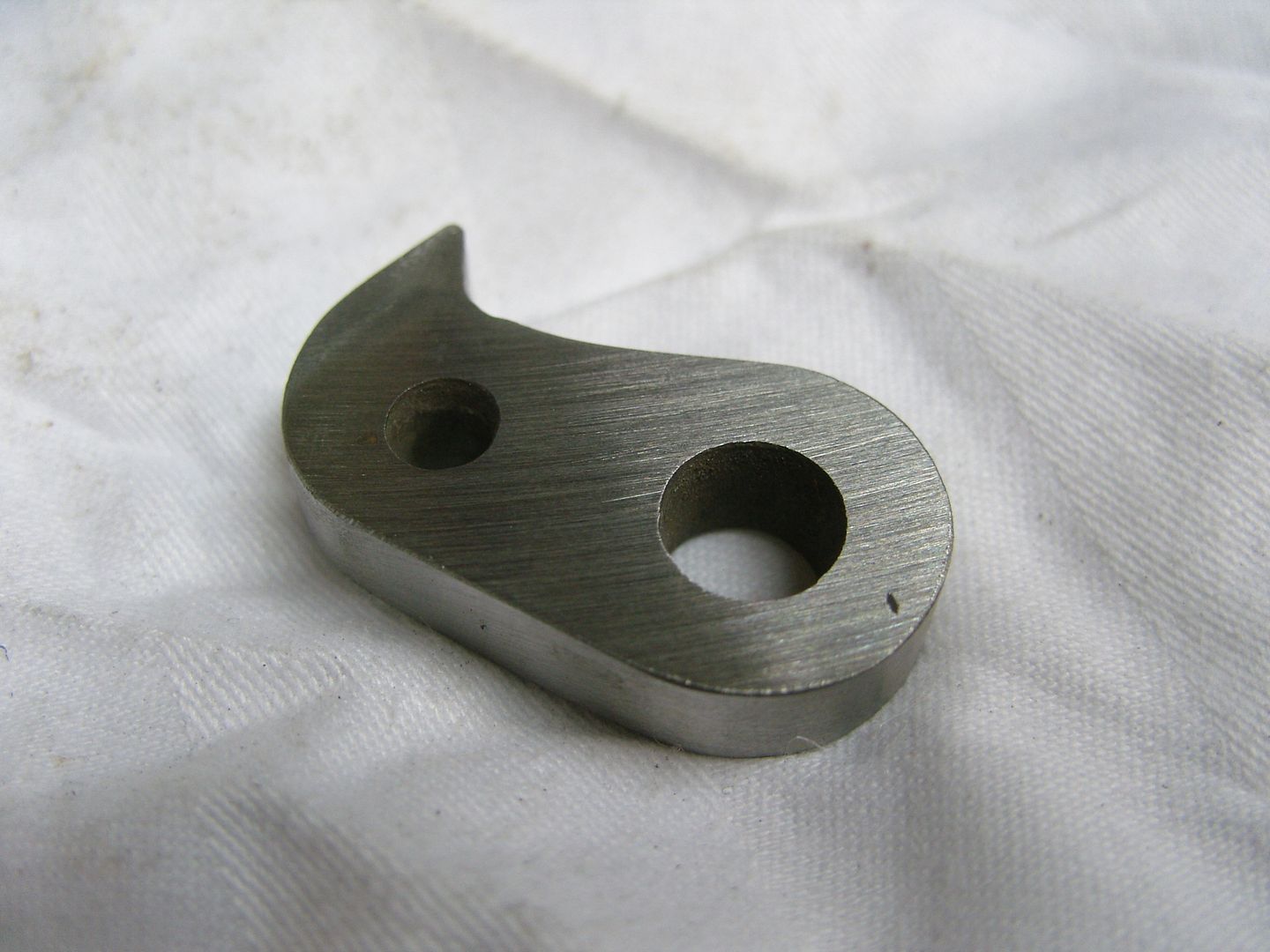
Along with my lights i got the door handles too, Its difficult to use the original handles on a glass car as the originals sort of clip into place so Willys parts have modified them and do a verson just for glass cars that bolt in place, pretty well designed so you only see the screw heads when the handle is turned. They are very nicely made with good chrome plating.
Original style fitting
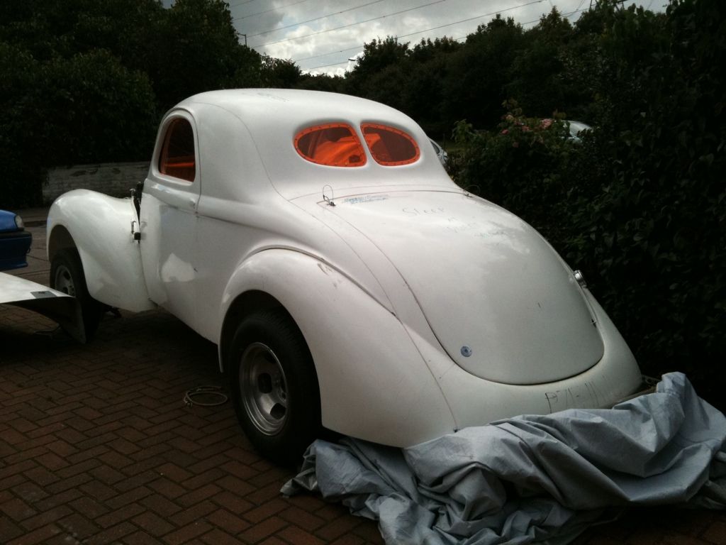
I also made a colour descision today, Ian (bigbossman had done several photoshops for me in satin blue & grey but they just didn't work and looked horrible, So see as its a 60's car I have gone for a dark blue mini flake., not sure the pic will give its true colour and sparkle.
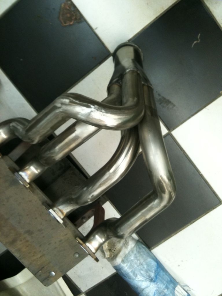
Someone commented that the header flanges didn't have enough room for the bolts so today i made a bit more headway with them and they are fine as i thought they would be.
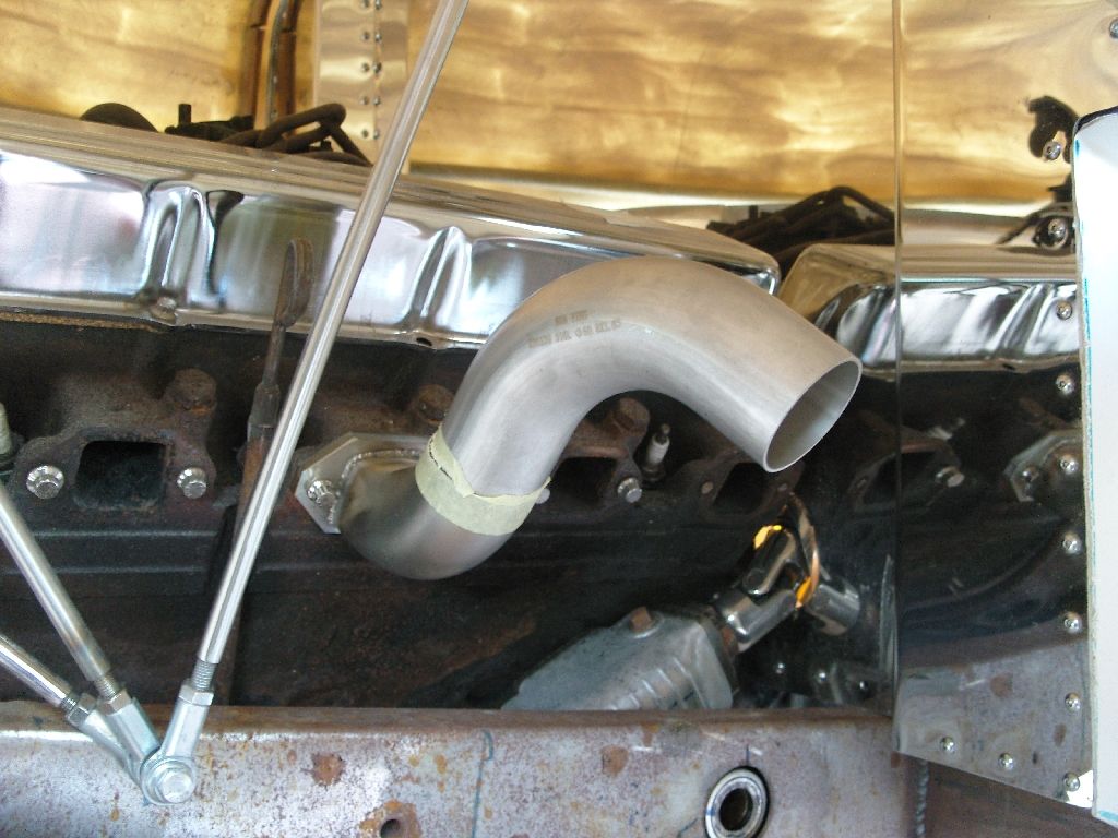
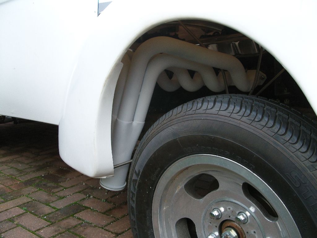
The last few evenings have been spent making up some fenderwell headers, these curve up and over to clear my side steering draglink, tube is 2 inch stainless 316L primaries, unfortunately i couldn't find any stainless collectors at a sensible price so i've used some mild steel ones from Summit Racing.
Some 1/4" plate was spun in the lathe to make the quick release caps and a stud mounted in the end of the collector to take a wing nut for securing, the standard wingnut will be changed for some larger custom made ones when i get around to making them.
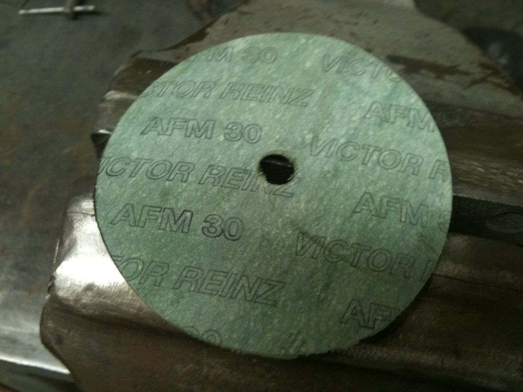
A gasket was cut from some Reinz boiler door gasket material.
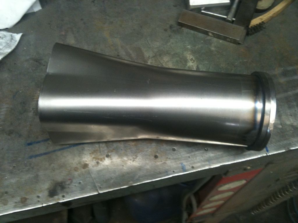
The primaries were started by squaring off the ends of the tube and welding to the flanges.
Sorry about the pic quality but had to use my phone.
ain't jetlag a wonderful thing Along with my lights i got the door handles too, Its difficult to use the original handles on a glass car as the originals sort of clip into place so Willys parts have modified them and do a verson just for glass cars that bolt in place, pretty well designed so you only see the screw heads when the handle is turned. They are very nicely made with good chrome plating.
Original style fitting
I also made a colour descision today, Ian (bigbossman had done several photoshops for me in satin blue & grey but they just didn't work and looked horrible, So see as its a 60's car I have gone for a dark blue mini flake., not sure the pic will give its true colour and sparkle.
Someone commented that the header flanges didn't have enough room for the bolts so today i made a bit more headway with them and they are fine as i thought they would be.
The last few evenings have been spent making up some fenderwell headers, these curve up and over to clear my side steering draglink, tube is 2 inch stainless 316L primaries, unfortunately i couldn't find any stainless collectors at a sensible price so i've used some mild steel ones from Summit Racing.
Some 1/4" plate was spun in the lathe to make the quick release caps and a stud mounted in the end of the collector to take a wing nut for securing, the standard wingnut will be changed for some larger custom made ones when i get around to making them.
A gasket was cut from some Reinz boiler door gasket material.
The primaries were started by squaring off the ends of the tube and welding to the flanges.
Sorry about the pic quality but had to use my phone.
langy
langys rodshop
- Messages
- 6,095
- Location
- London
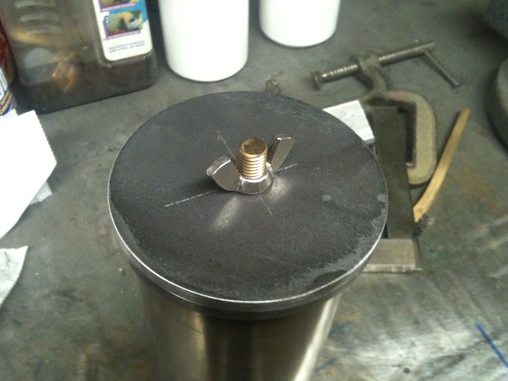
As I said earlier the wingnuts were temporary, after searching the net for some tri eared spinners and not finding anything suitable i decided to make some instead.
First i started with some stainless acorn nuts and turned off the hexagon part, next some ears were cut from 3/16" stainless and blended & fettled and pre polished, next a small jig was made for TIG welding them, then more polishing, then i had some custom tri bar wingnuts that i could tighten by hand
cheers
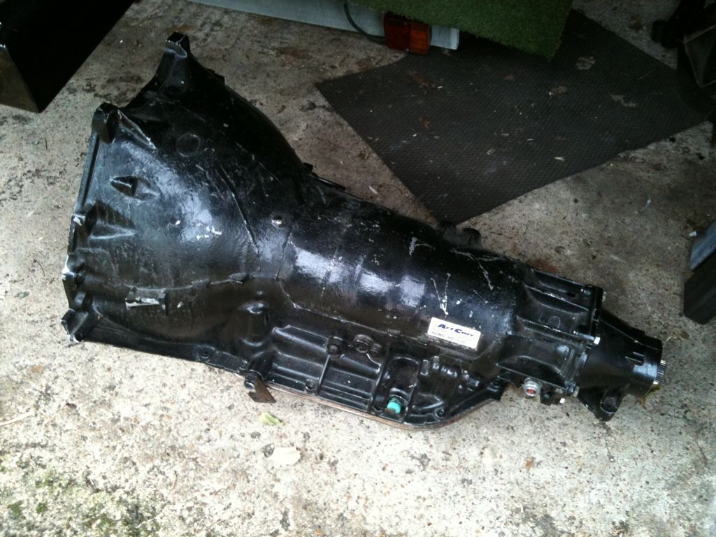
Thanks to Jason (fatguyz) who collected my TH400 from Steve & Mitch (thanks boys) who in turn collected it from Zane at Zannetec (more thanks Zane)
I bought the Art Carr with Transbrake box secondhand with 2nd gear slipping and Zane kindly rebuilt it for me, I would highly recommend Zane he does an excellent job and is a nice old boy too
Over the Autumn i need to strip it back to bare aluminium and epoxy prime and paint Porsche India Red to match the motor and also fit the larger capacity aluminium trans pan i have.
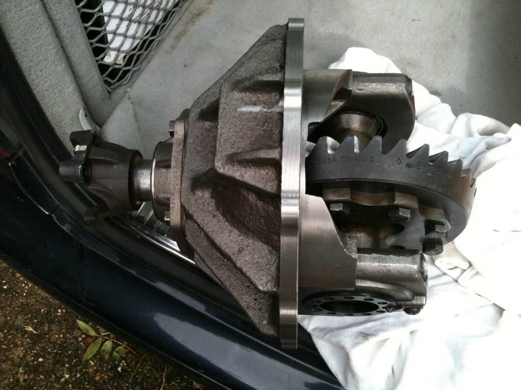
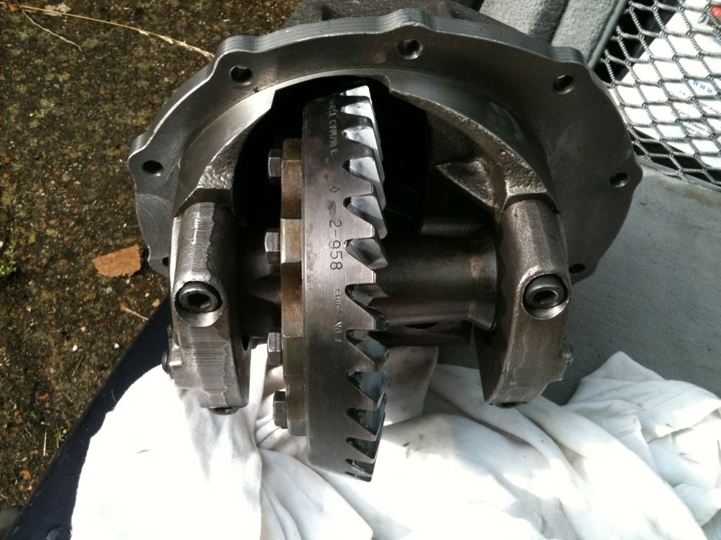
Another recommendation is for Paul at Southern Axles, Paul has been racing for years and knows his stuff, His shop is only a block away from mine so was the obvious choice to assemble the axle parts i had collected, Diff case is a brand new item with 3.89 Zoom gears mounted on a 31 spline Spool, with a 1350 yoke, all new bearings etc etc, again this needs to be epoxy primed and painted, i'm not sure what colour the back axle is gonna be yet, suggestions welcomed.
First i started with some stainless acorn nuts and turned off the hexagon part, next some ears were cut from 3/16" stainless and blended & fettled and pre polished, next a small jig was made for TIG welding them, then more polishing, then i had some custom tri bar wingnuts that i could tighten by hand
cheers
Thanks to Jason (fatguyz) who collected my TH400 from Steve & Mitch (thanks boys) who in turn collected it from Zane at Zannetec (more thanks Zane)
I bought the Art Carr with Transbrake box secondhand with 2nd gear slipping and Zane kindly rebuilt it for me, I would highly recommend Zane he does an excellent job and is a nice old boy too
Over the Autumn i need to strip it back to bare aluminium and epoxy prime and paint Porsche India Red to match the motor and also fit the larger capacity aluminium trans pan i have.
Another recommendation is for Paul at Southern Axles, Paul has been racing for years and knows his stuff, His shop is only a block away from mine so was the obvious choice to assemble the axle parts i had collected, Diff case is a brand new item with 3.89 Zoom gears mounted on a 31 spline Spool, with a 1350 yoke, all new bearings etc etc, again this needs to be epoxy primed and painted, i'm not sure what colour the back axle is gonna be yet, suggestions welcomed.
langy
langys rodshop
- Messages
- 6,095
- Location
- London
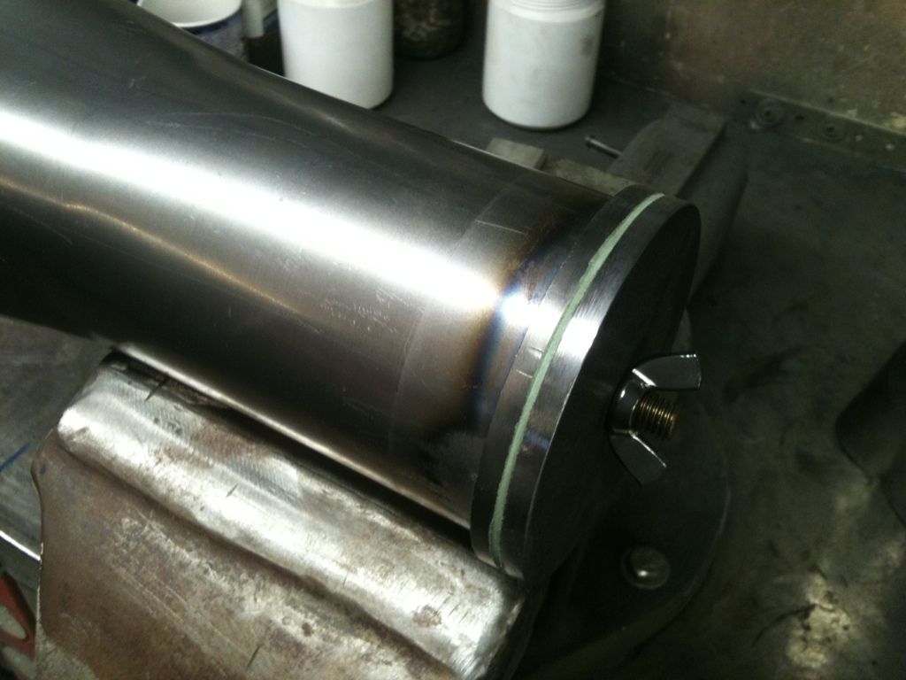
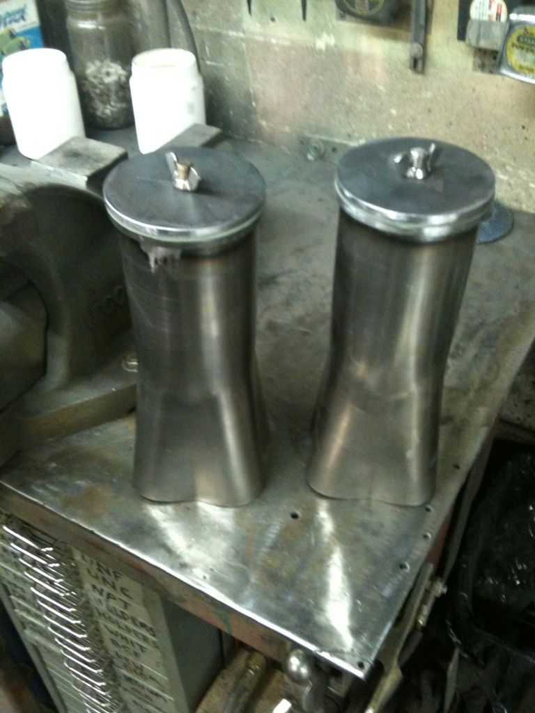
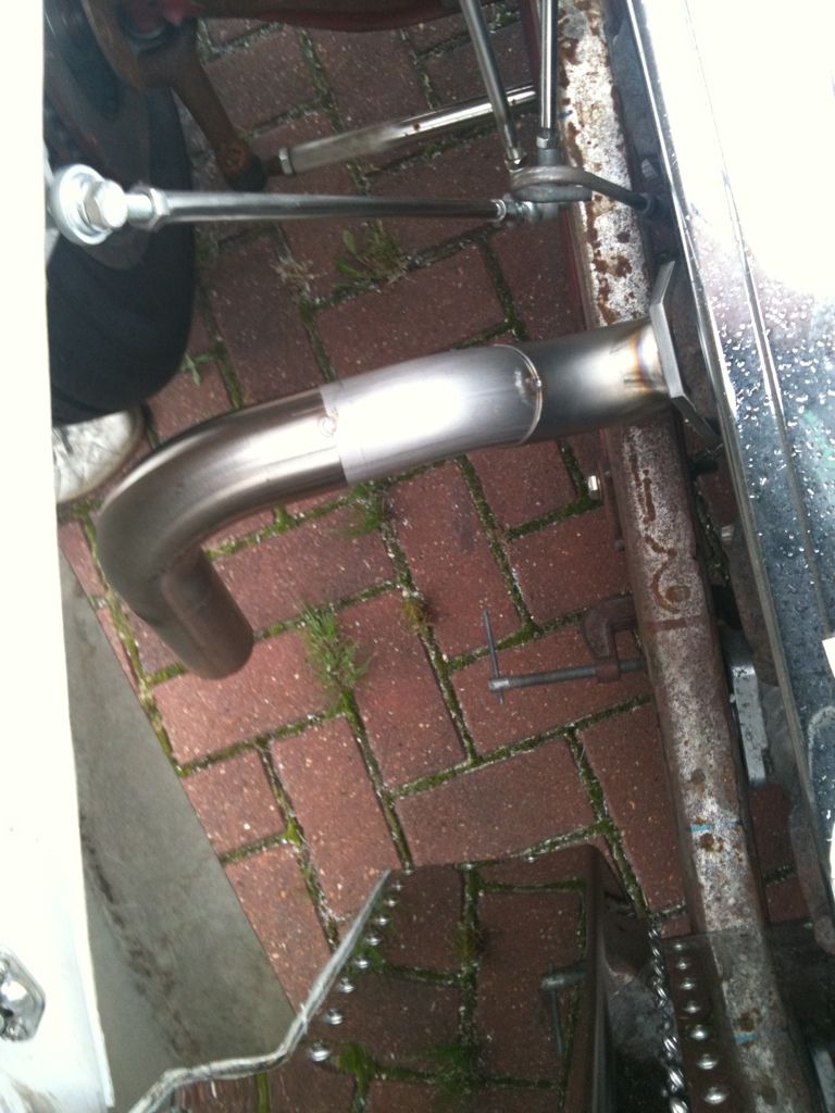
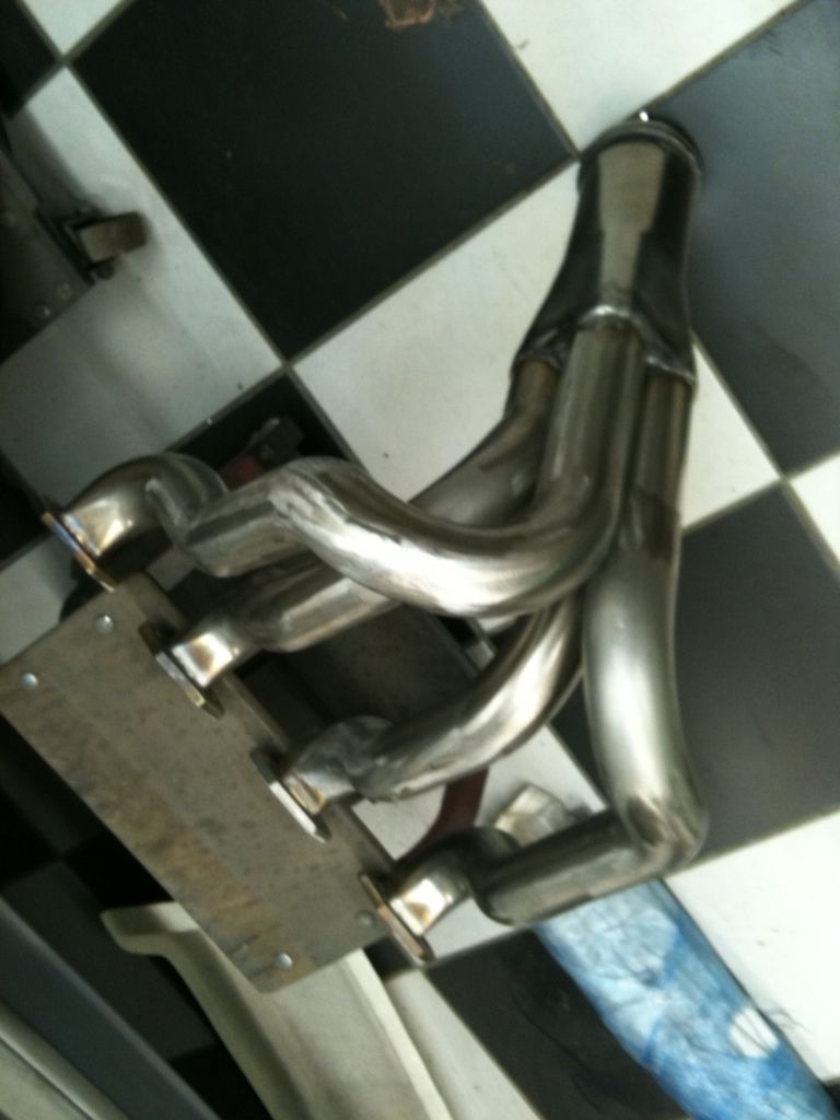
On saturday i finally finished the drivers side header, took longer than i thought !!! Now the really hard part is making the other side match.
I just wanted the bottom of the collector showing and easy access to the wing nut for uncapping.
Its getting dark early now, winters coming !!!
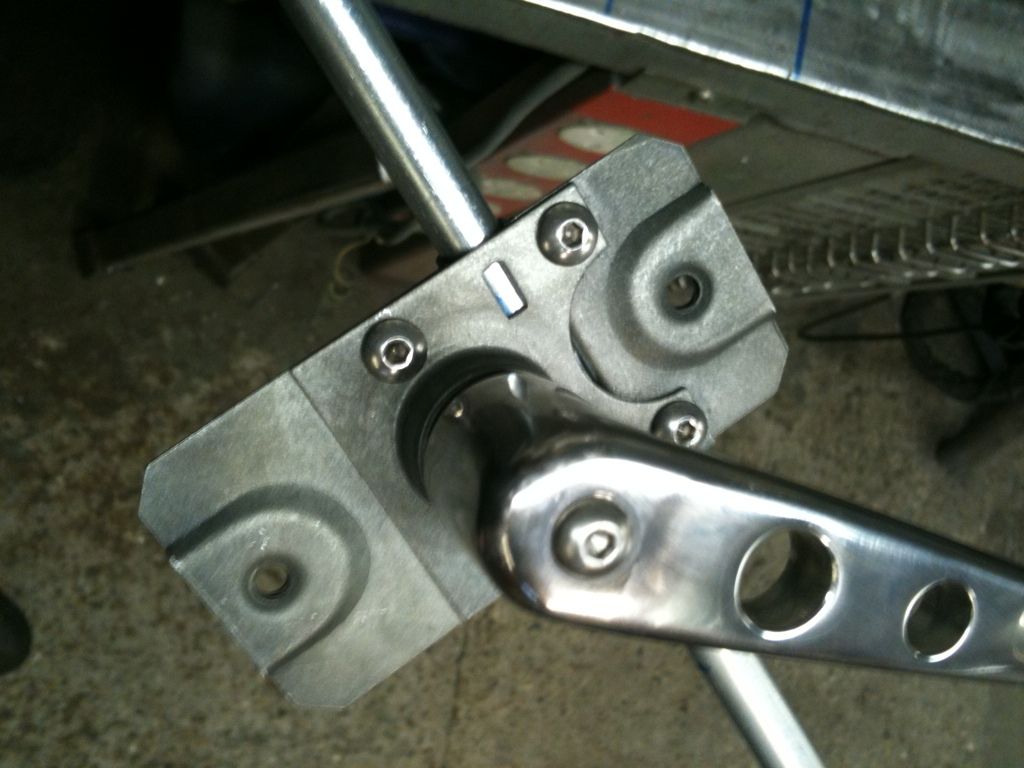
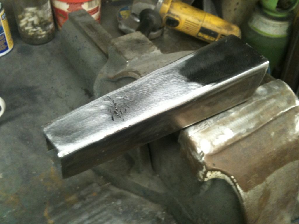
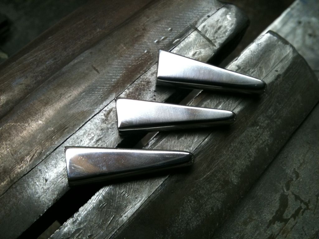
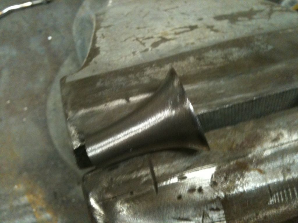
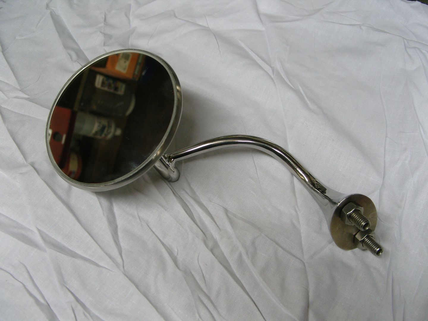
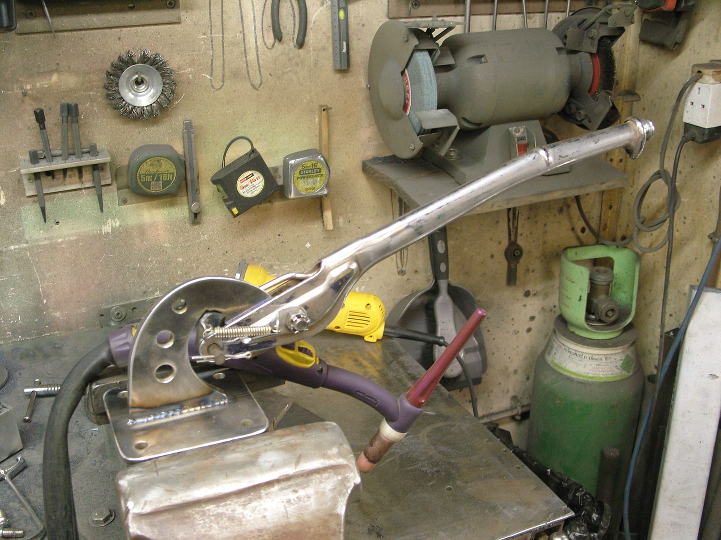
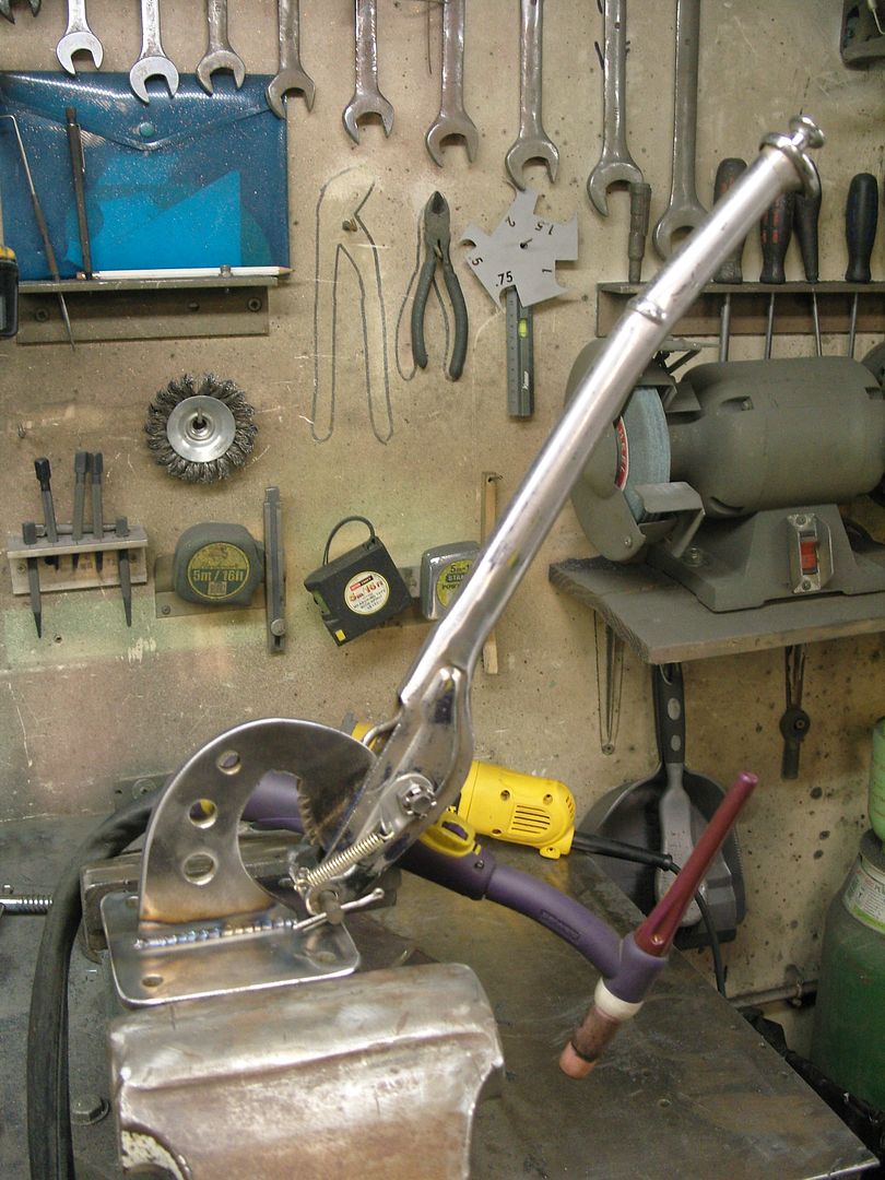
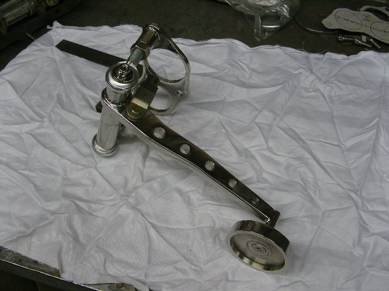
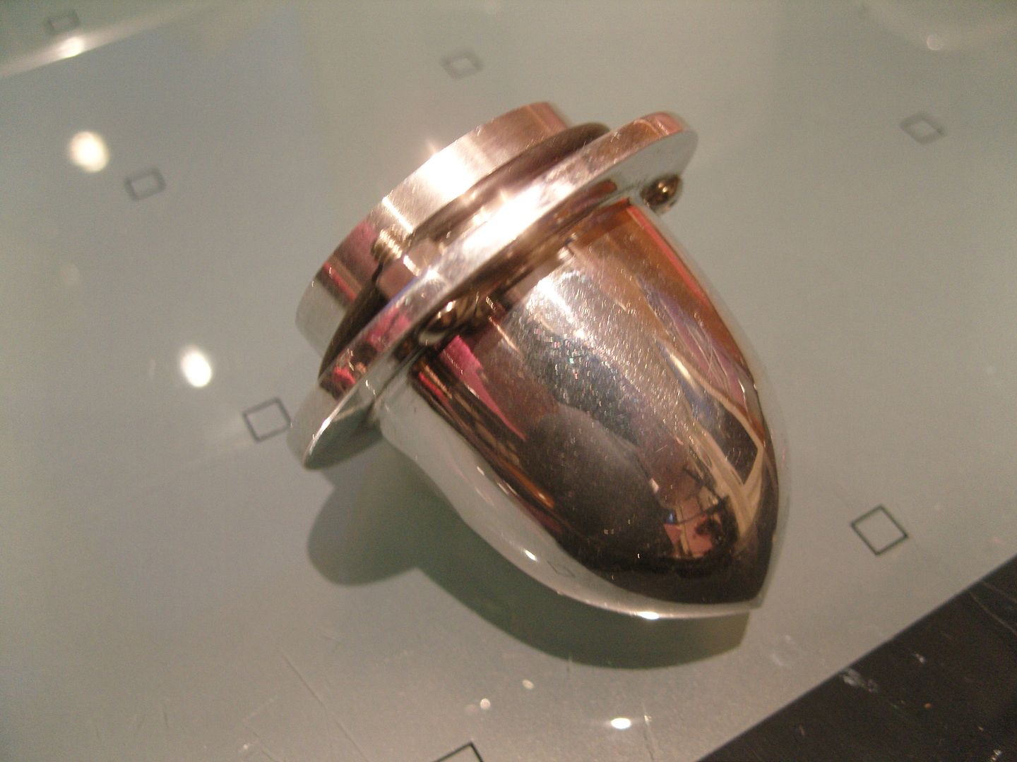
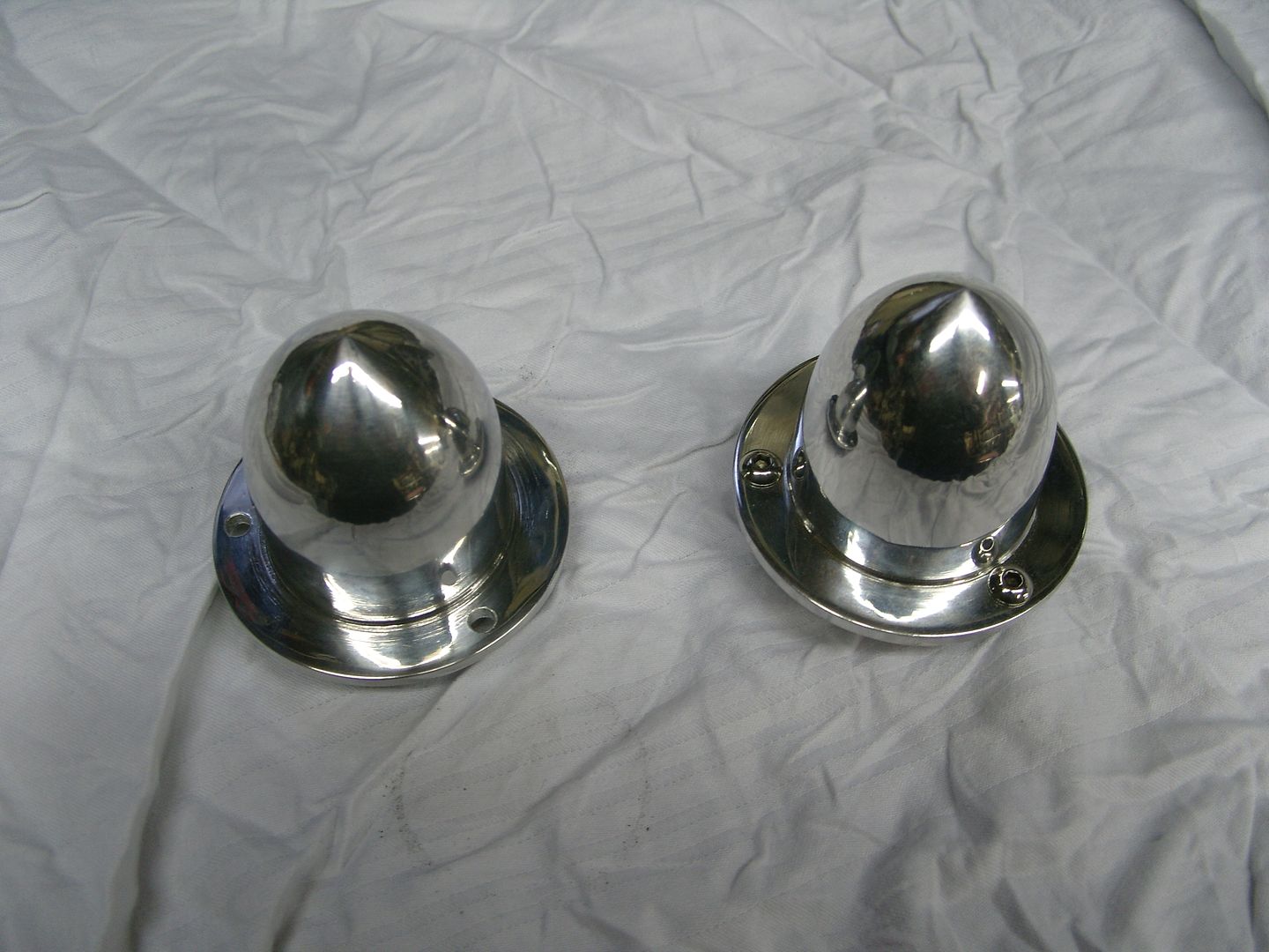
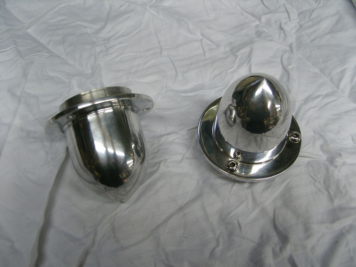
While i've been nursing a fractured elbow i've been getting a few of the smaller jobs out of the way, A couple of nights ago i realised i would need an exterior door mirror, l looked through all my Willys pics but didn't see one so decided to design my own.
They are made from 316L stainless and were pretty easy to make really.
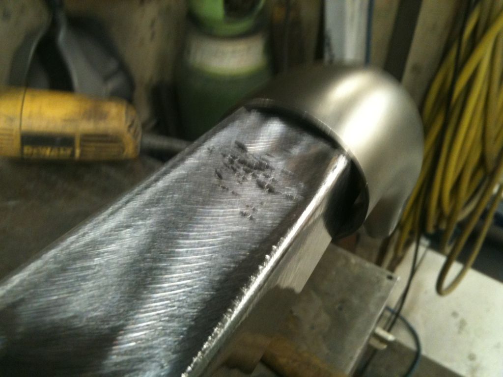
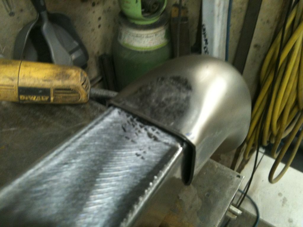
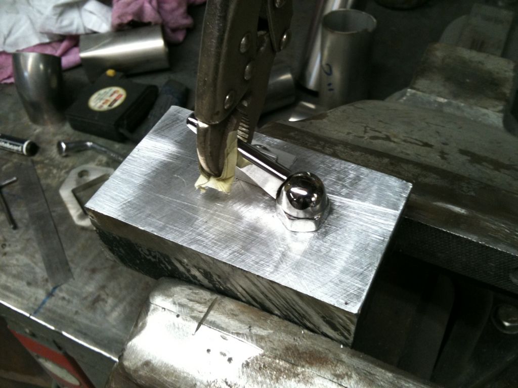
I started by making a trumpet shaped base piece, I didn't have any 2" OD bar so had to make the piece out of some 1" bar and add a piece of 3/8" plate to the bottom and sculpture it in, 2 x 5/16" grub screws were fitted in the base to attach to the door

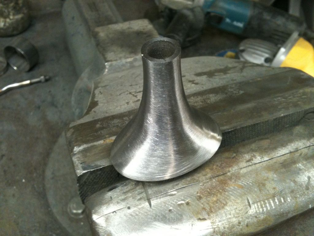
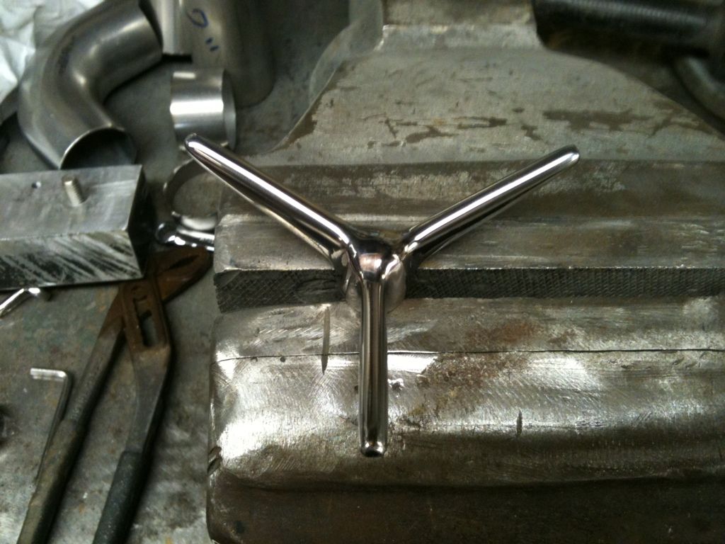
I was then stuck as i had run out of 1/2" bar foe the arm until my mate Allan came over with a piece, The bar was turned in the lathe to a taper of 5/15" at the small end gradually increasing to 1/2" the other, While he was there he helped me with the bending of the arm which was warmed with a Mapp gaz torch. once the arm was welded to the base i made up a top piece for retaining the mirror head and i metal finished it ready for polishing.
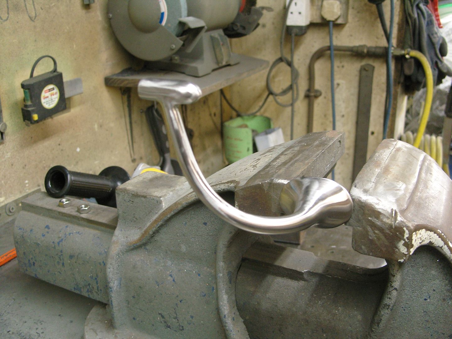
Next job was to start the polishing process of finer and finer grits and then dull polish with a Sisal wheel and finally bringing to a full shine with a cotton Stitch mop. Sorry about the pics but the camera don't like the polished surface.
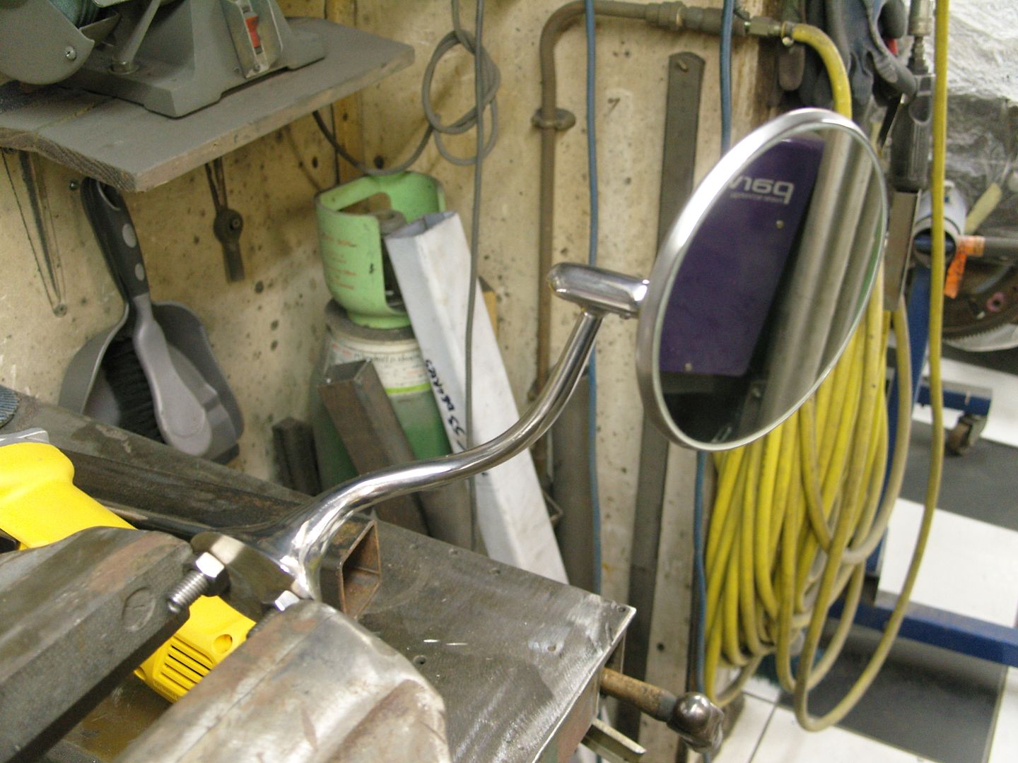
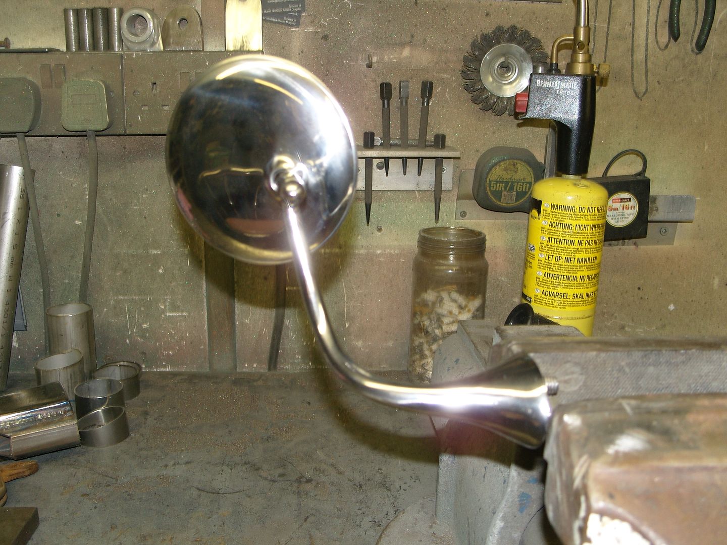
These pics are better
:cheers:
I just wanted the bottom of the collector showing and easy access to the wing nut for uncapping.
Its getting dark early now, winters coming !!!
While i've been nursing a fractured elbow i've been getting a few of the smaller jobs out of the way, A couple of nights ago i realised i would need an exterior door mirror, l looked through all my Willys pics but didn't see one so decided to design my own.
They are made from 316L stainless and were pretty easy to make really.
I started by making a trumpet shaped base piece, I didn't have any 2" OD bar so had to make the piece out of some 1" bar and add a piece of 3/8" plate to the bottom and sculpture it in, 2 x 5/16" grub screws were fitted in the base to attach to the door
I was then stuck as i had run out of 1/2" bar foe the arm until my mate Allan came over with a piece, The bar was turned in the lathe to a taper of 5/15" at the small end gradually increasing to 1/2" the other, While he was there he helped me with the bending of the arm which was warmed with a Mapp gaz torch. once the arm was welded to the base i made up a top piece for retaining the mirror head and i metal finished it ready for polishing.
Next job was to start the polishing process of finer and finer grits and then dull polish with a Sisal wheel and finally bringing to a full shine with a cotton Stitch mop. Sorry about the pics but the camera don't like the polished surface.
These pics are better
:cheers:
langy
langys rodshop
- Messages
- 6,095
- Location
- London
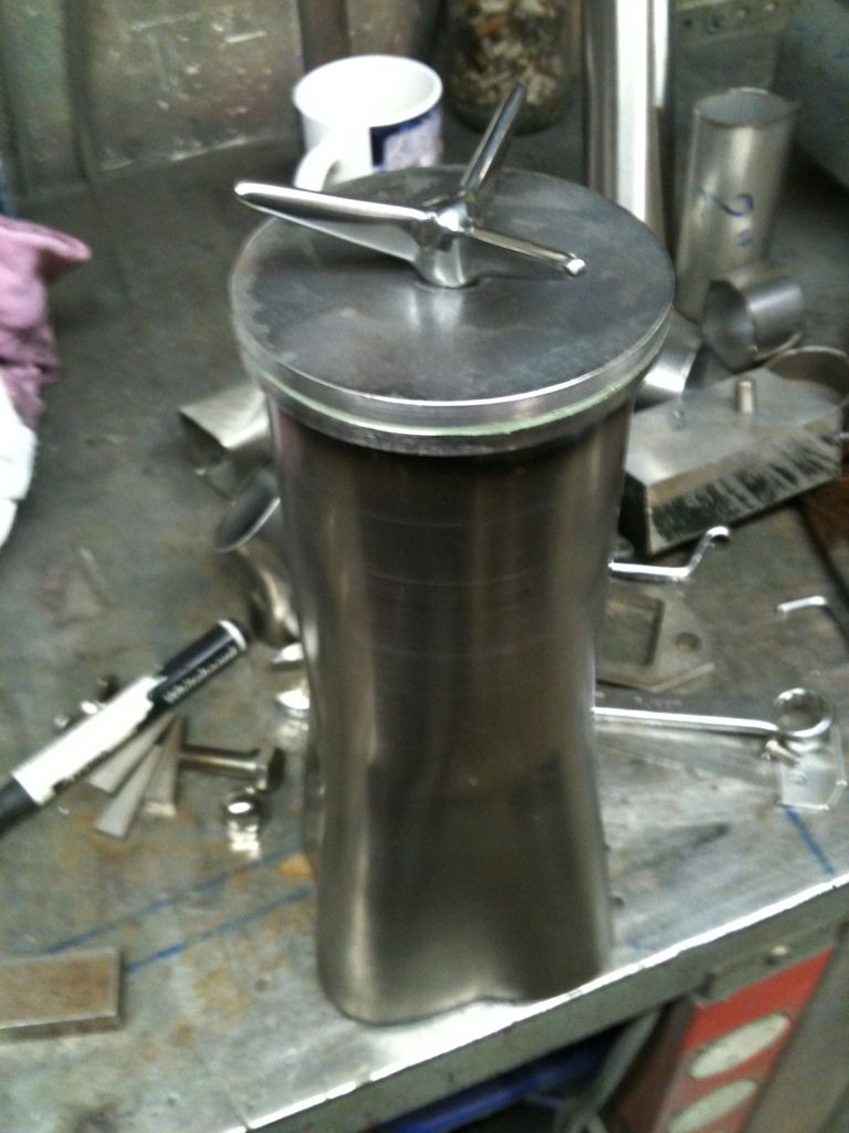
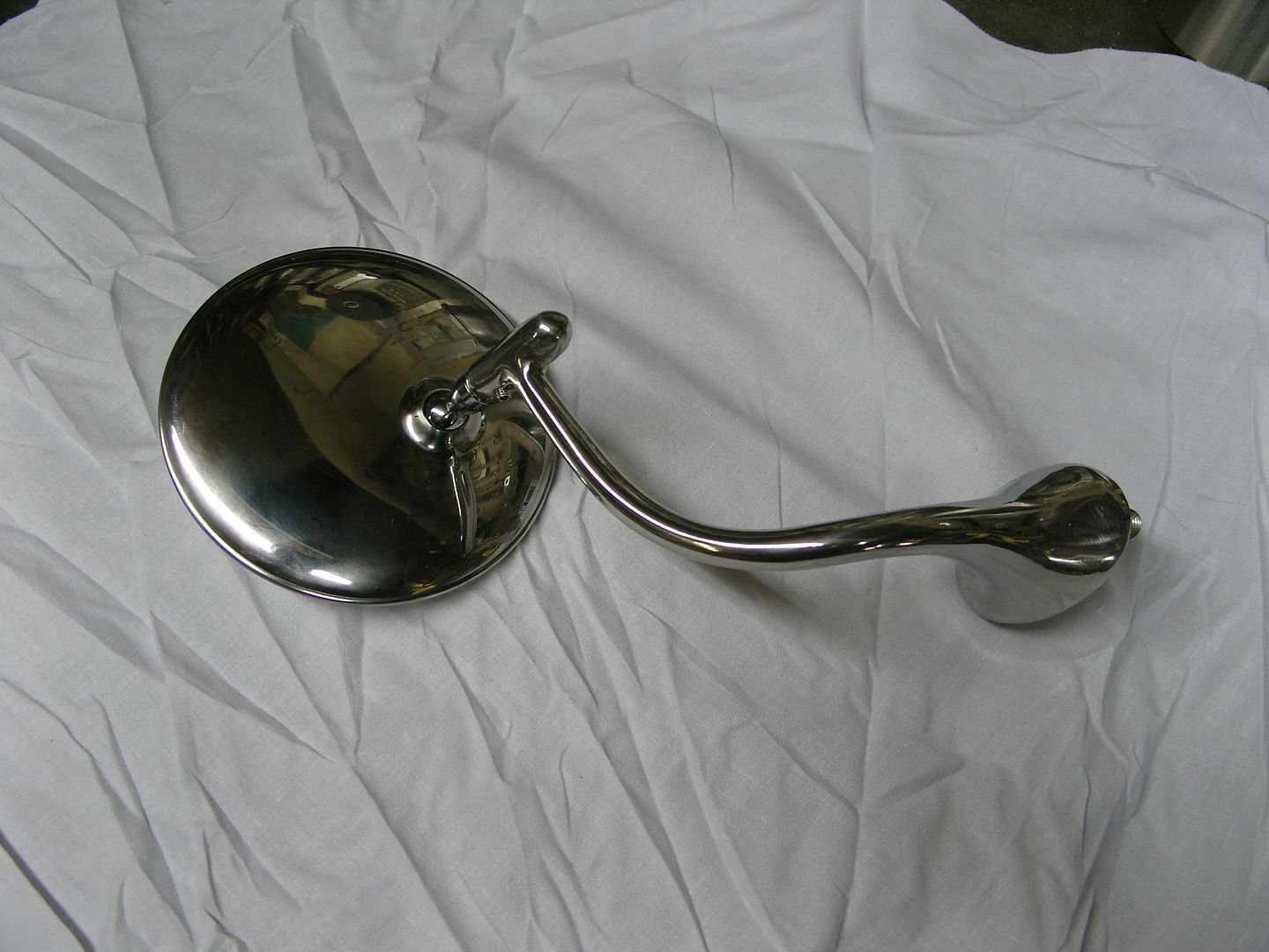
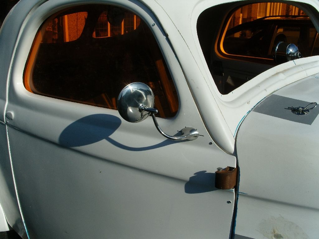
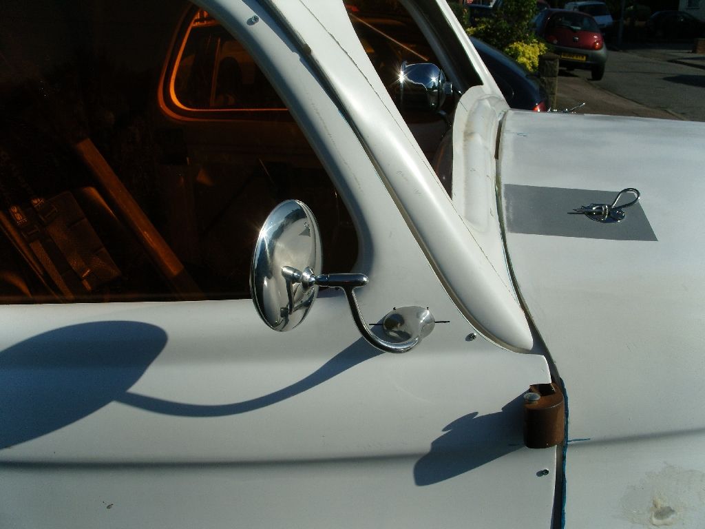
I put the mirror on last night to get a better idea how it looked, I'm happy with it.
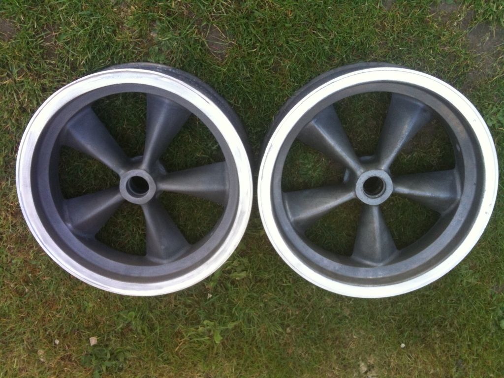
I'm in a bit of a dilemma as i just got offered 2 new front wheels, they are A.R.E. 5 spoke magnesium spindle mounts, 4" x 15", they are complete with spindles, bearings, discs and calipers, they have been offered to me at a cheaper price than what they are advertised at, do I or don't I ???
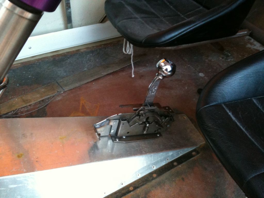
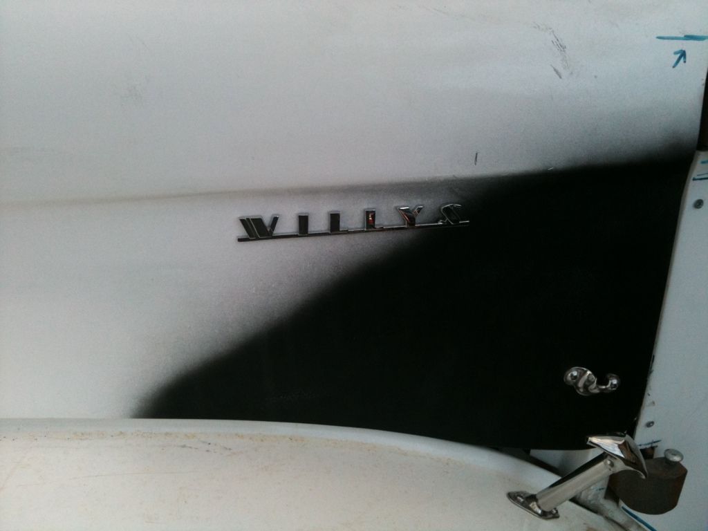
Well winter draws closer and its now dark at 6pm so progress is slowing rapidly but i picked up a B&M Quick Silver shifter cheap, been butchered in a couple of places but sorted that out and fitted it to the trans tunnel with rivnuts, Oh and decided to fit the Willys badges i had.
Thought i had better sort a handbrake, luckily i had an old upright handbrake lever from a old 1950's bus ( I knew i would use it someday)
The lever was 3ft long so first job was to shorten it to a nice comfortable length.
1st pic is what i started with.
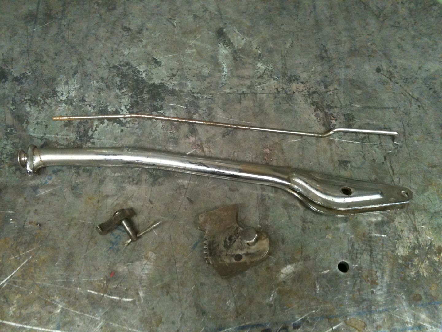
Next on the list was a floor mounted bracket, someone had butchered the mechanism before i got it so i made an upright and welded the ratchet piece to it.
The pawl was pretty badly worn so i made another from steel, heated it to cherry red and quenched it in water to harden it.
Heres the bits laid out before reassembly
1st pic is fully closed and 2nd pic fully open. I was gonna cover it with a leather gaiter but thought it would look cool left open and chromed.
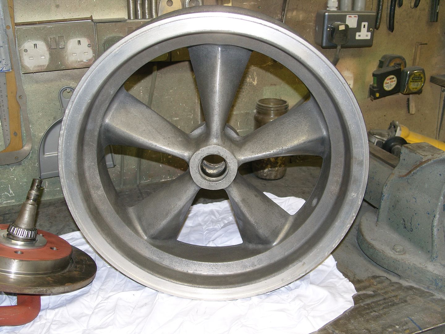
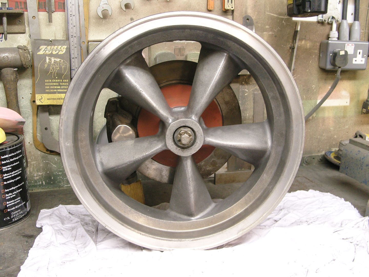
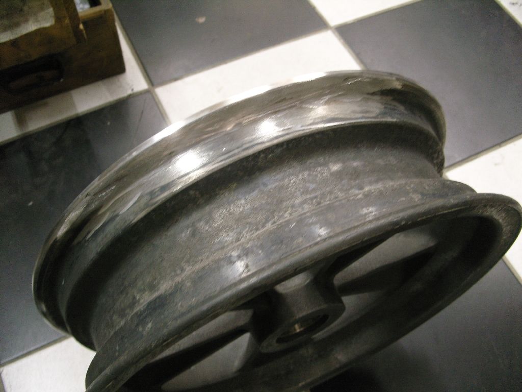
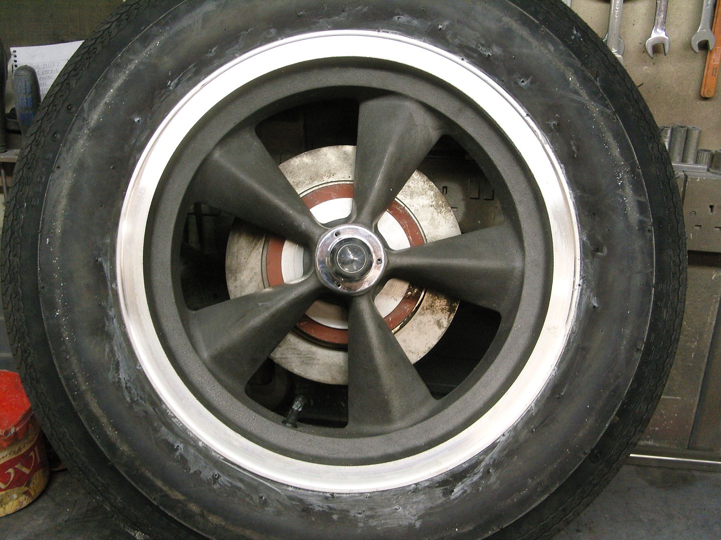
I also treated the old girl to a pair of ARE magnesium spindle mount 5 spoke 4" x 15" front wheels, these came with discs and calipers, bearing etc but need a little bit of fitting to complete.
Also got the other header done and finished.
.
I'm in a bit of a dilemma as i just got offered 2 new front wheels, they are A.R.E. 5 spoke magnesium spindle mounts, 4" x 15", they are complete with spindles, bearings, discs and calipers, they have been offered to me at a cheaper price than what they are advertised at, do I or don't I ???
Well winter draws closer and its now dark at 6pm so progress is slowing rapidly but i picked up a B&M Quick Silver shifter cheap, been butchered in a couple of places but sorted that out and fitted it to the trans tunnel with rivnuts, Oh and decided to fit the Willys badges i had.
Thought i had better sort a handbrake, luckily i had an old upright handbrake lever from a old 1950's bus ( I knew i would use it someday)
The lever was 3ft long so first job was to shorten it to a nice comfortable length.
1st pic is what i started with.
Next on the list was a floor mounted bracket, someone had butchered the mechanism before i got it so i made an upright and welded the ratchet piece to it.
The pawl was pretty badly worn so i made another from steel, heated it to cherry red and quenched it in water to harden it.
Heres the bits laid out before reassembly
1st pic is fully closed and 2nd pic fully open. I was gonna cover it with a leather gaiter but thought it would look cool left open and chromed.
I also treated the old girl to a pair of ARE magnesium spindle mount 5 spoke 4" x 15" front wheels, these came with discs and calipers, bearing etc but need a little bit of fitting to complete.
Also got the other header done and finished.
.
langy
langys rodshop
- Messages
- 6,095
- Location
- London
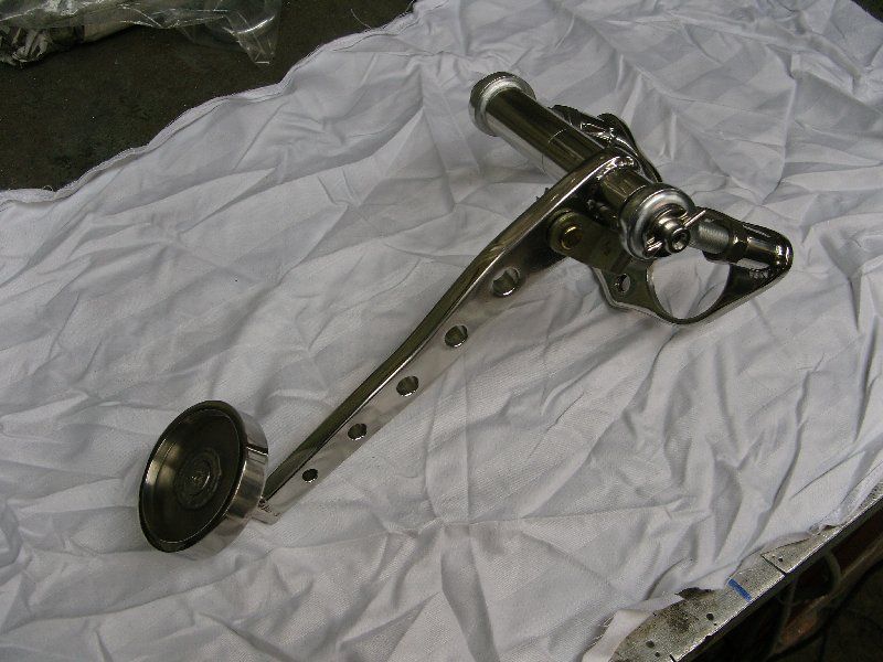
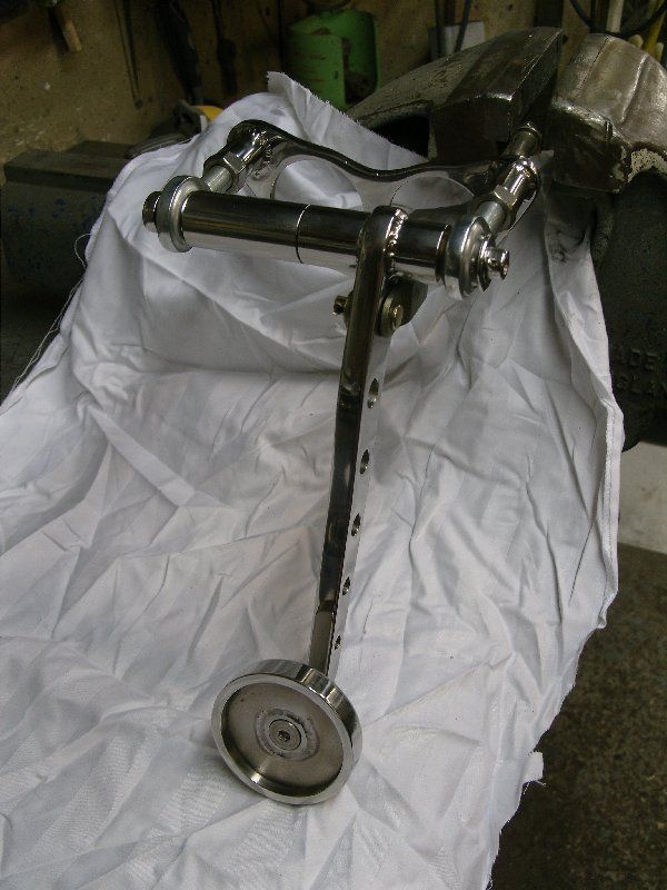
Well the last couple of evenings i've managed to sort a job that i couldn't make my mind up about, namely the brake pedal, the sensible side of me was saying under the floor dual circuit master cylinder but i just thought it looked to modern, the other side was saying swinging pedals and 1960 Chevy picup master cylinder, the one drawback was that it as single circuit but as i already had a brand new cylinder i decided to go the unsensible route.
Obviously to use this cylinder i needed a swinging pedal box, the Ansen type fitted my needs perfectly and used the chevy master but after seeing the prices they were going for i decided to make my own.
One problem arose straightaway as i knew i had a master cylinder but forgot i had sold it to a customer, a quick call and another was on its way and the customer kindly sent me a template of the cylinder base bolt pattern, this at least enabled me to get started.
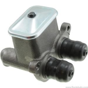
This is the 60-62 Chevy cylinder i'm using.
This is the expensive & rare Ansen pedal box
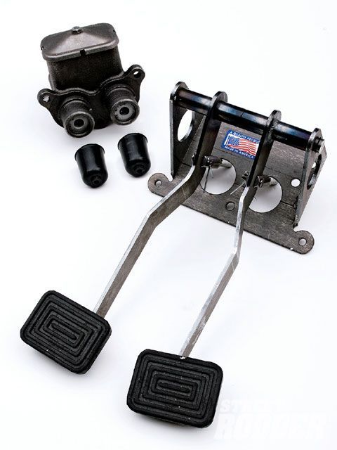
My version is made from 316L stainless, base is 1/4" cut from plate (not laser cut) pedal is 3/8" and as its on display i polished it all, master cylinder mounts on firewall. Mine is also adjustable
Obviously to use this cylinder i needed a swinging pedal box, the Ansen type fitted my needs perfectly and used the chevy master but after seeing the prices they were going for i decided to make my own.
One problem arose straightaway as i knew i had a master cylinder but forgot i had sold it to a customer, a quick call and another was on its way and the customer kindly sent me a template of the cylinder base bolt pattern, this at least enabled me to get started.
This is the 60-62 Chevy cylinder i'm using.
This is the expensive & rare Ansen pedal box
My version is made from 316L stainless, base is 1/4" cut from plate (not laser cut) pedal is 3/8" and as its on display i polished it all, master cylinder mounts on firewall. Mine is also adjustable
langy
langys rodshop
- Messages
- 6,095
- Location
- London
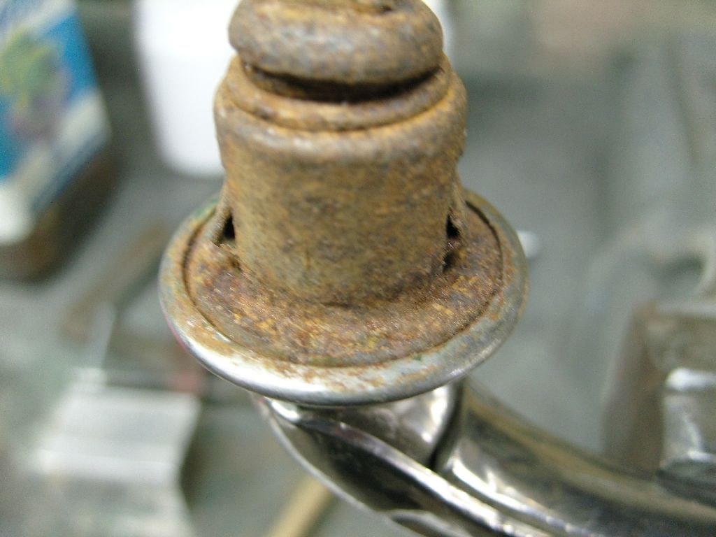
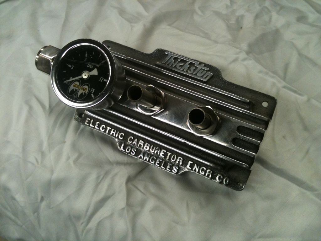
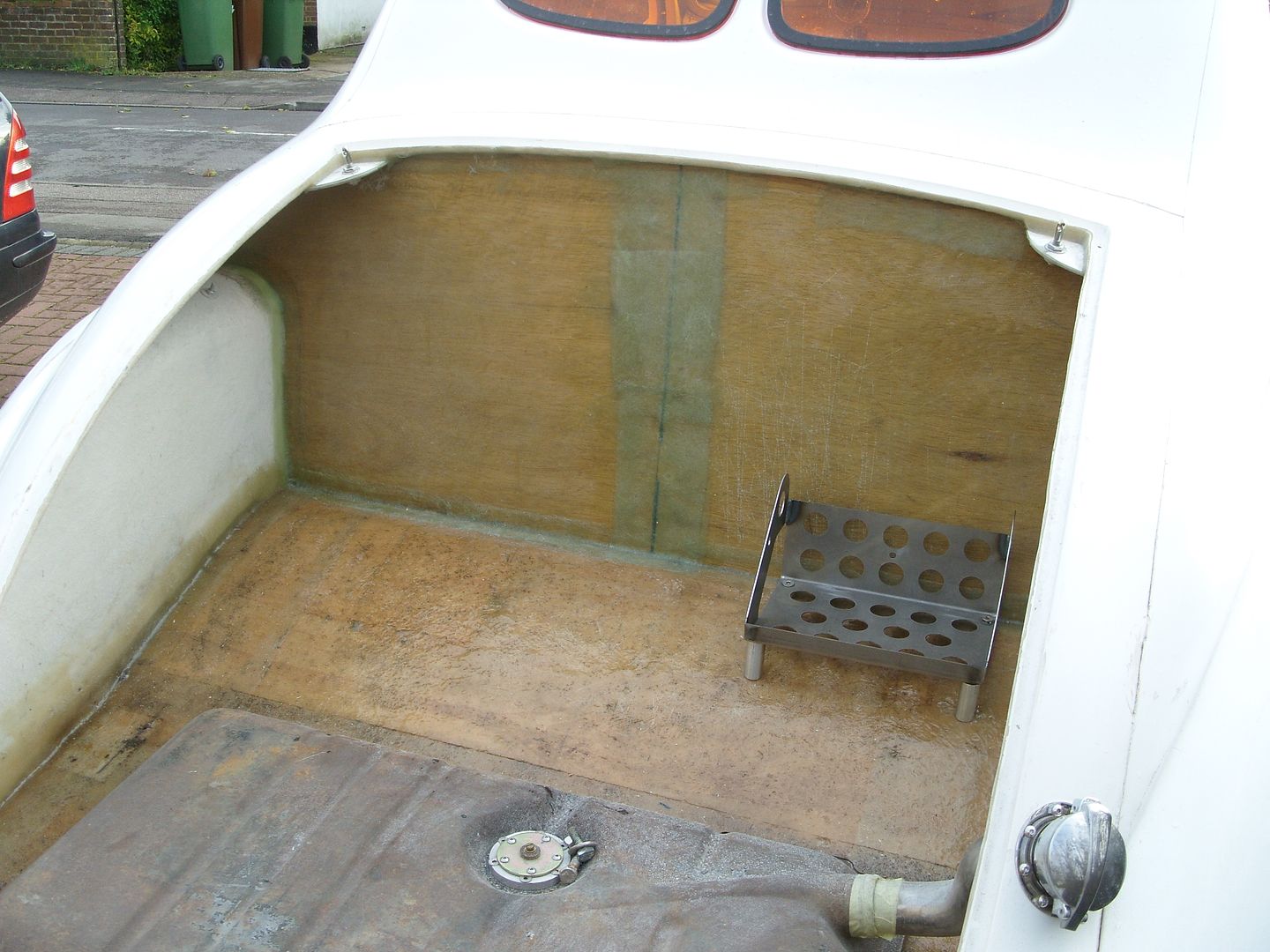
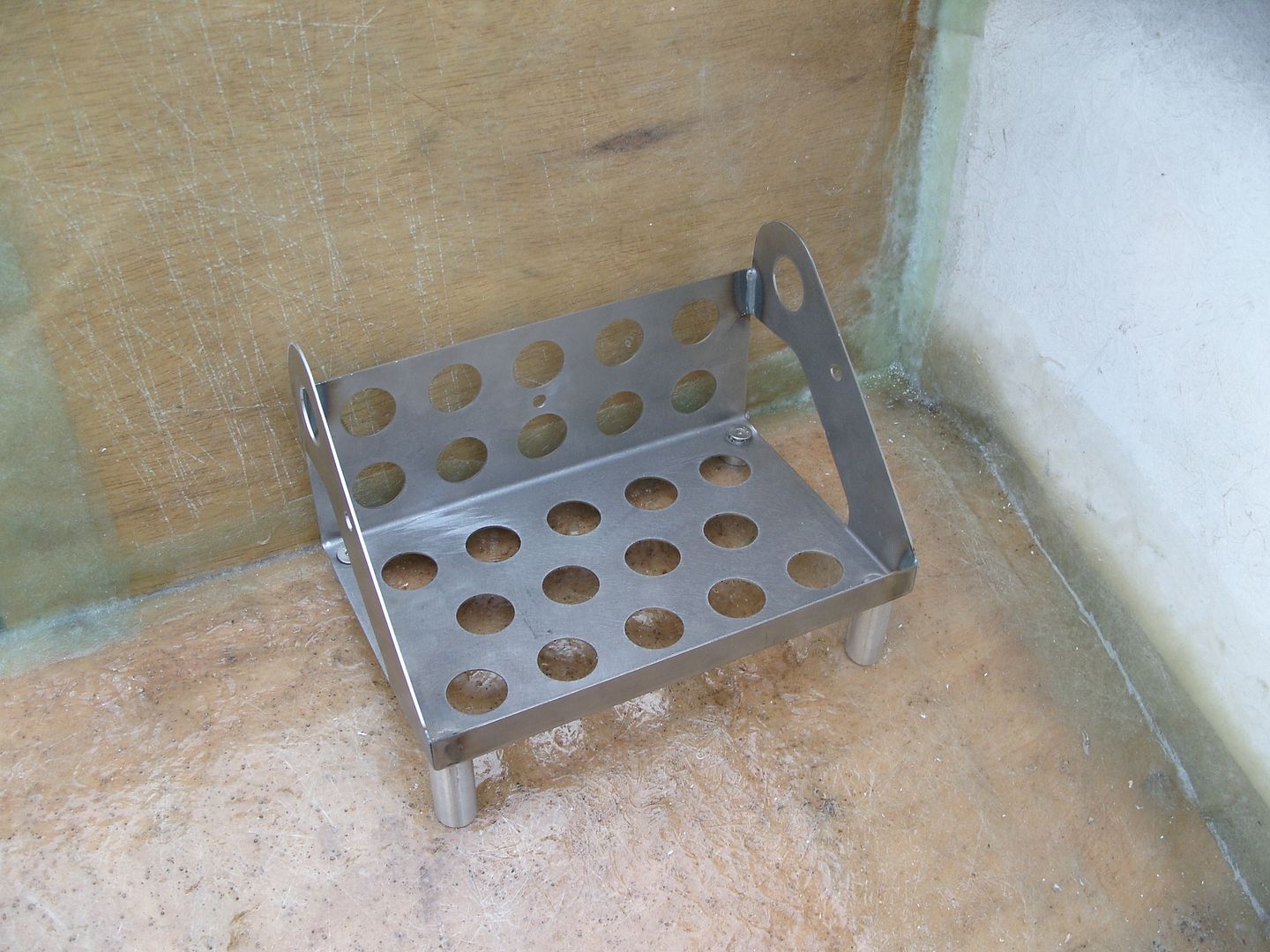
Had a spare couple of hours tonight so thought i would sort my fuel block, I picked it up ages ago in the states and is an old Thickstun block, I only bought it as i thought it looked cool !!!
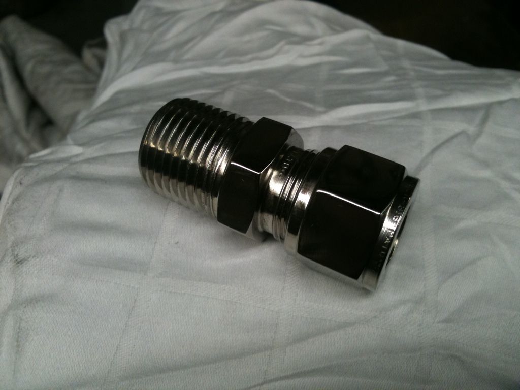
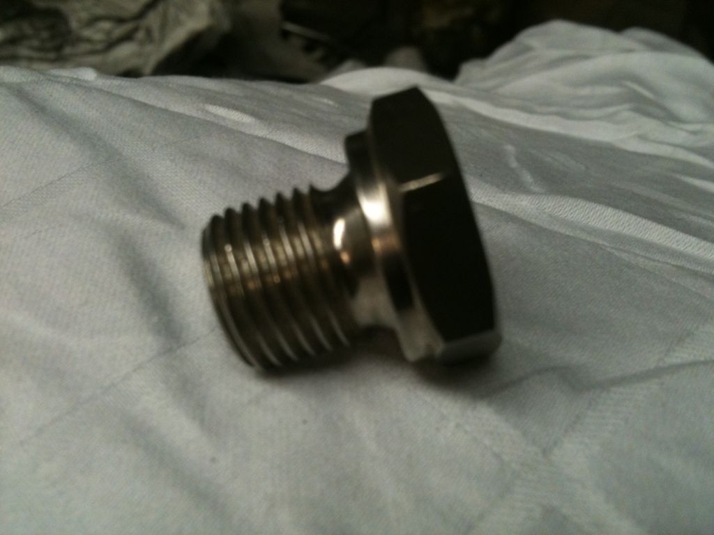
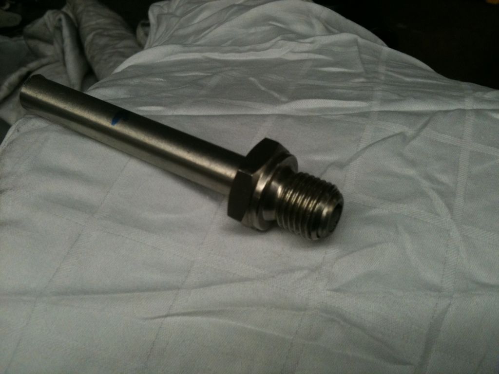
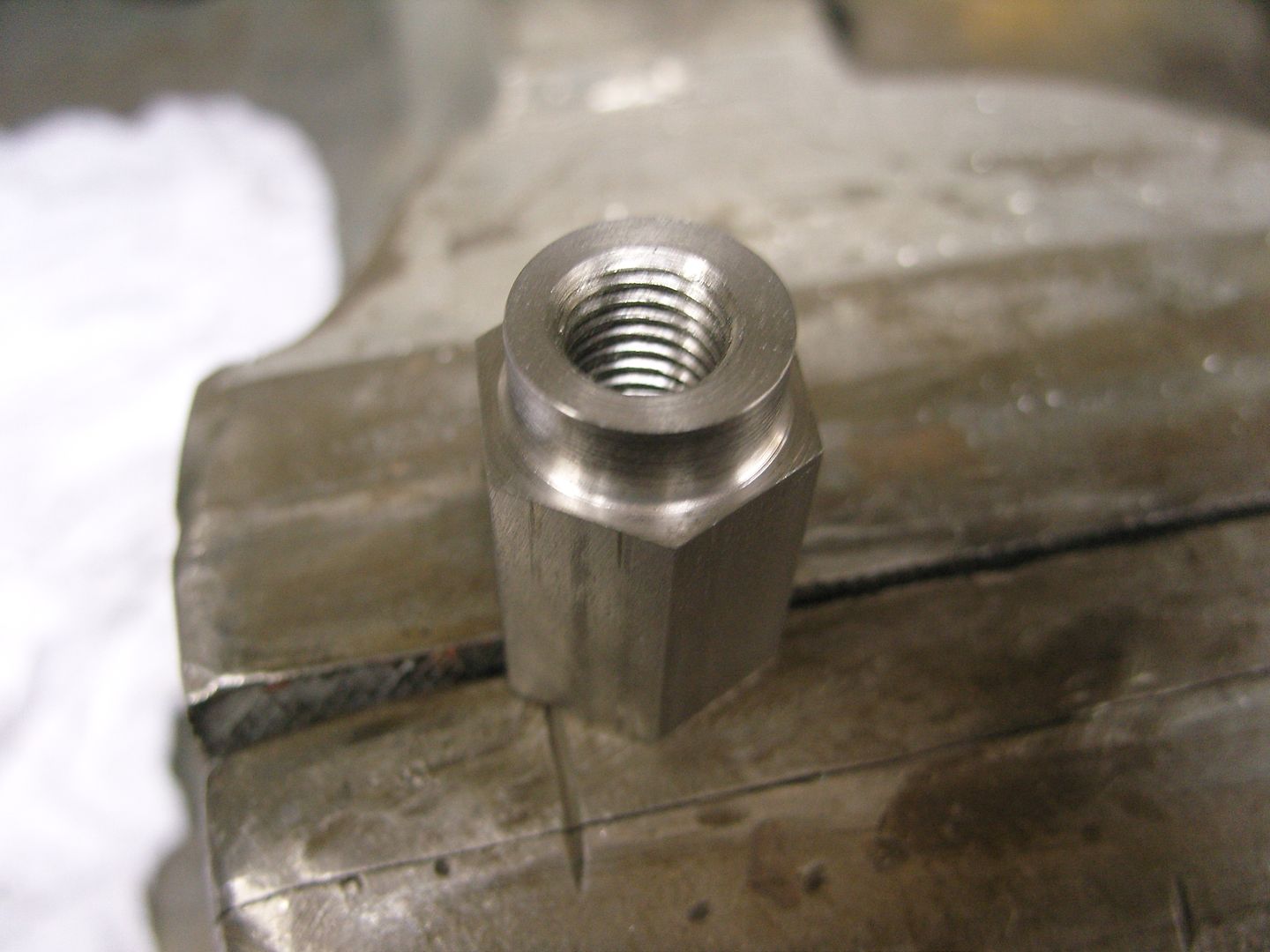
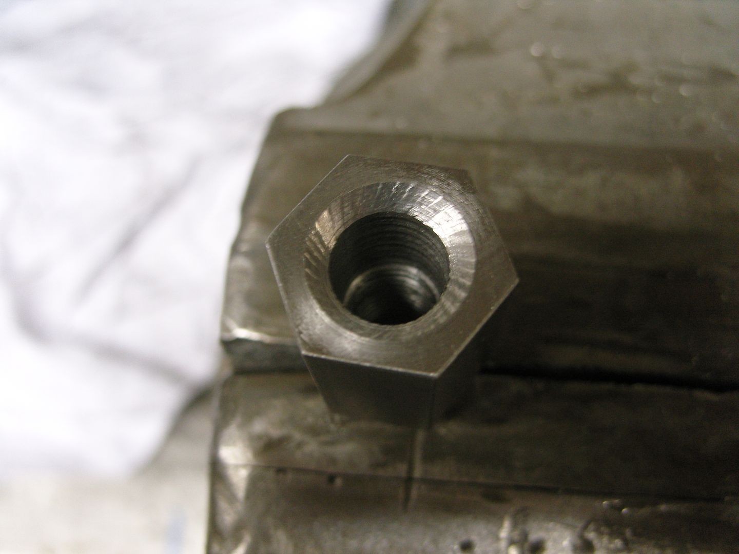
Anyway it was on the shelf so thought i would use it, first job was to drill out the main passage to 1/2" as thats the size of my main fuel line. Then i found a 1/2" stainless fitting with 1/2" NPT thread so drilled and tapped the entry port, the exit ports were a little more tricky as i wanted to use stainless fittings to match but couldn't find them in the right size.
Had to make some on the lathe in the end and weld in short lengths of tube, I didn't have a NPT die so I put a 1/2" UNF thread on them and seal them with a copper washer.
Added a Moon fuel pressure gauge and its ready to rock.
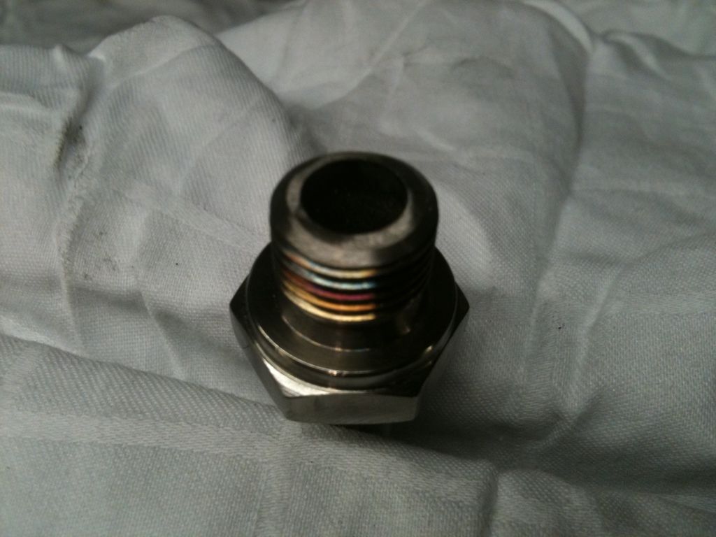
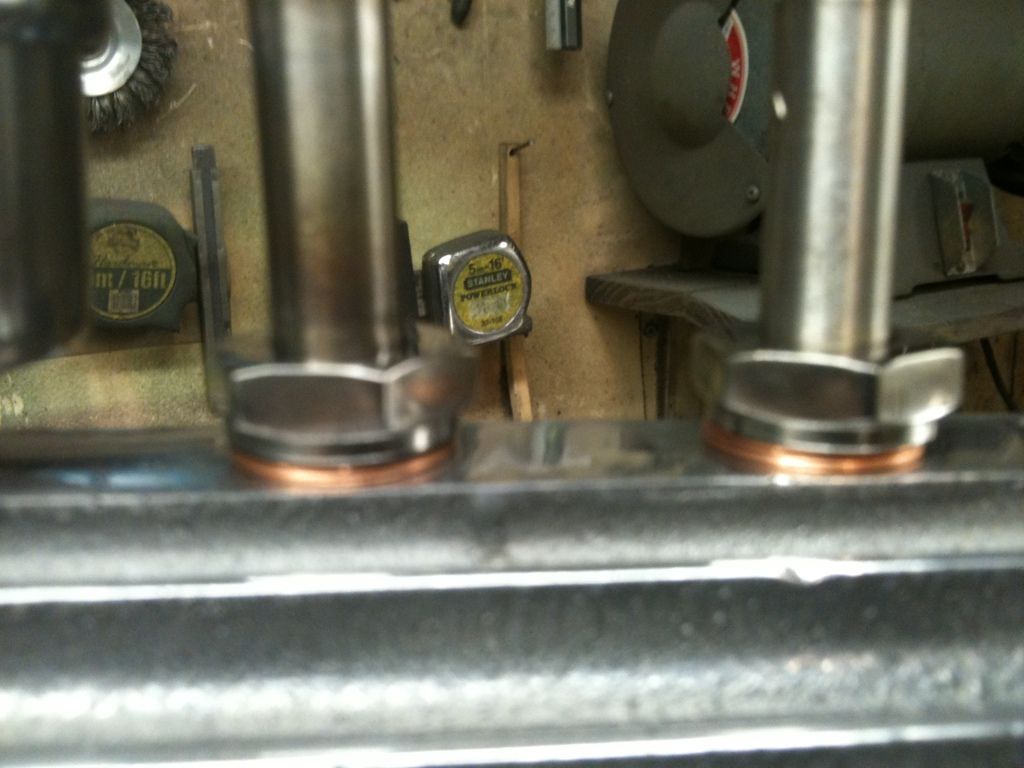
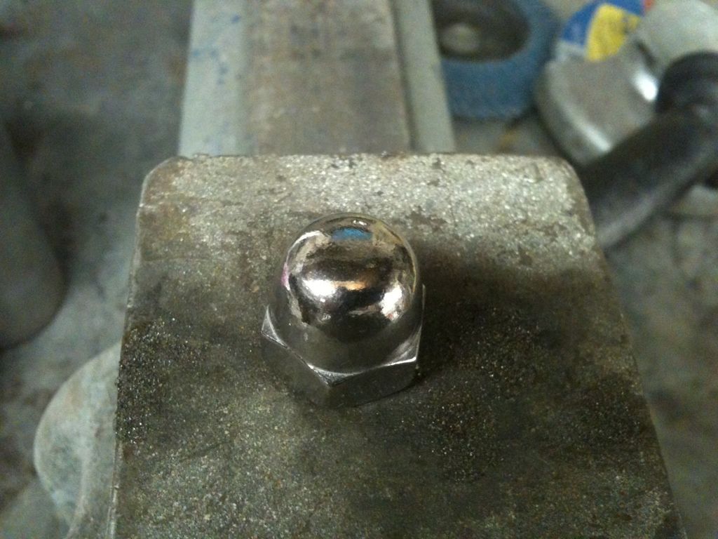
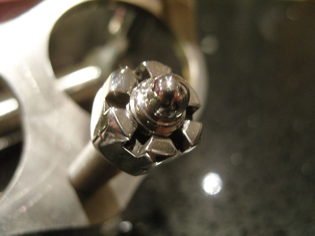
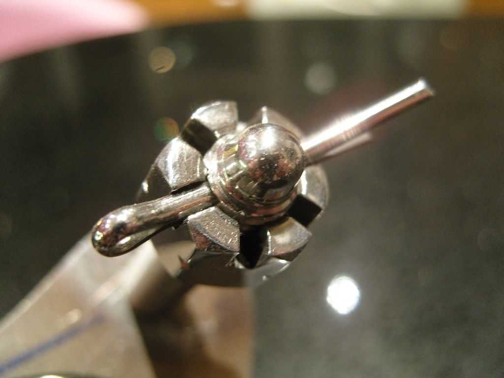
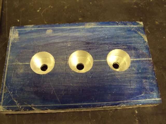
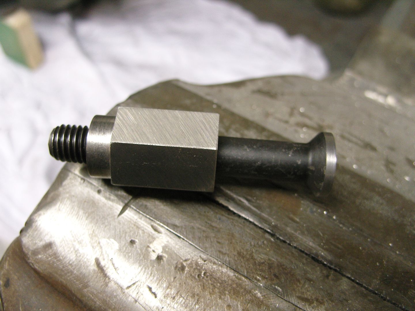
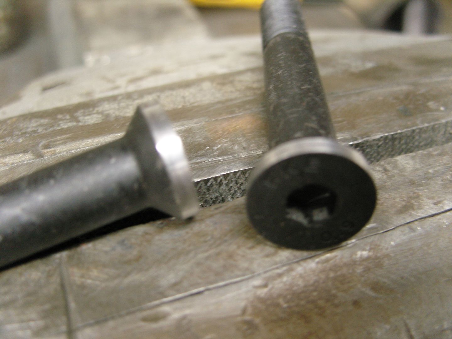
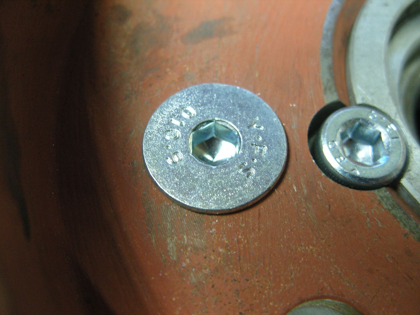
I maybe the only one but been thinking about finishing the ends of bolts where the nut sits in a different way, nothing too difficult to do but looking for something cool and different, I ground a lathe tool to the required shape so it could be done in one process to save time.
Heres what i came up with.
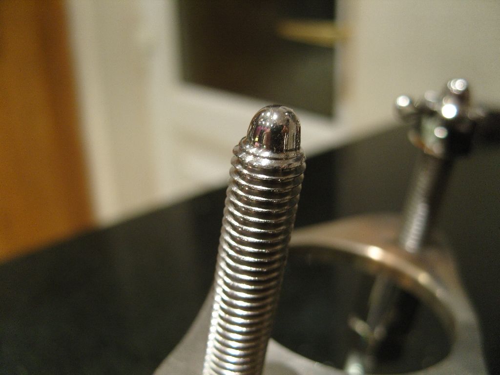
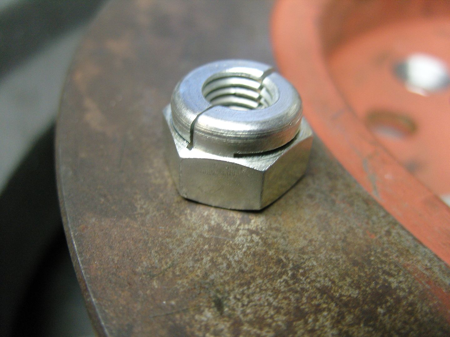
When used with a Castellated nut it takes on a nice different look.
Anyway it was on the shelf so thought i would use it, first job was to drill out the main passage to 1/2" as thats the size of my main fuel line. Then i found a 1/2" stainless fitting with 1/2" NPT thread so drilled and tapped the entry port, the exit ports were a little more tricky as i wanted to use stainless fittings to match but couldn't find them in the right size.
Had to make some on the lathe in the end and weld in short lengths of tube, I didn't have a NPT die so I put a 1/2" UNF thread on them and seal them with a copper washer.
Added a Moon fuel pressure gauge and its ready to rock.
I maybe the only one but been thinking about finishing the ends of bolts where the nut sits in a different way, nothing too difficult to do but looking for something cool and different, I ground a lathe tool to the required shape so it could be done in one process to save time.
Heres what i came up with.
When used with a Castellated nut it takes on a nice different look.
langy
langys rodshop
- Messages
- 6,095
- Location
- London
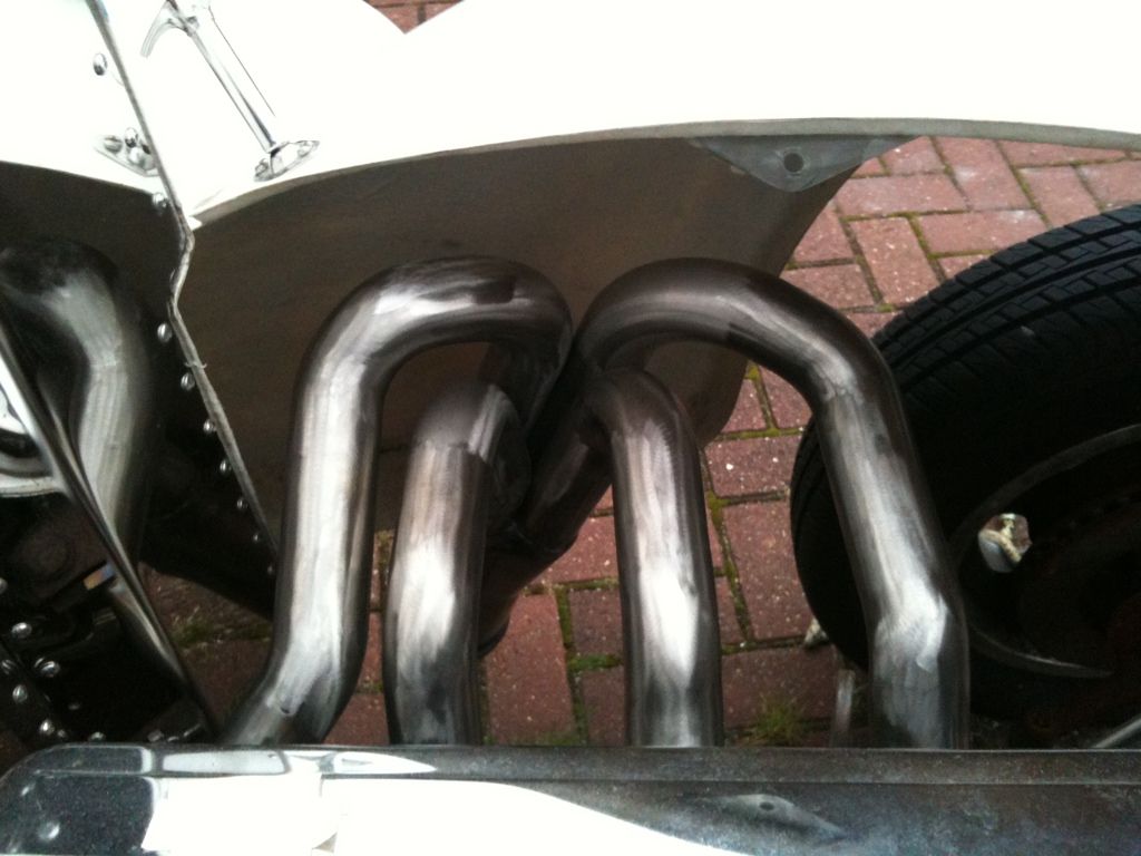
Mostly bits & pieces done today, nothing worth a picture but i did get my headers done in white and wanted to see what they looked like so bolted them on with a few bolts, Its just the look i wanted.
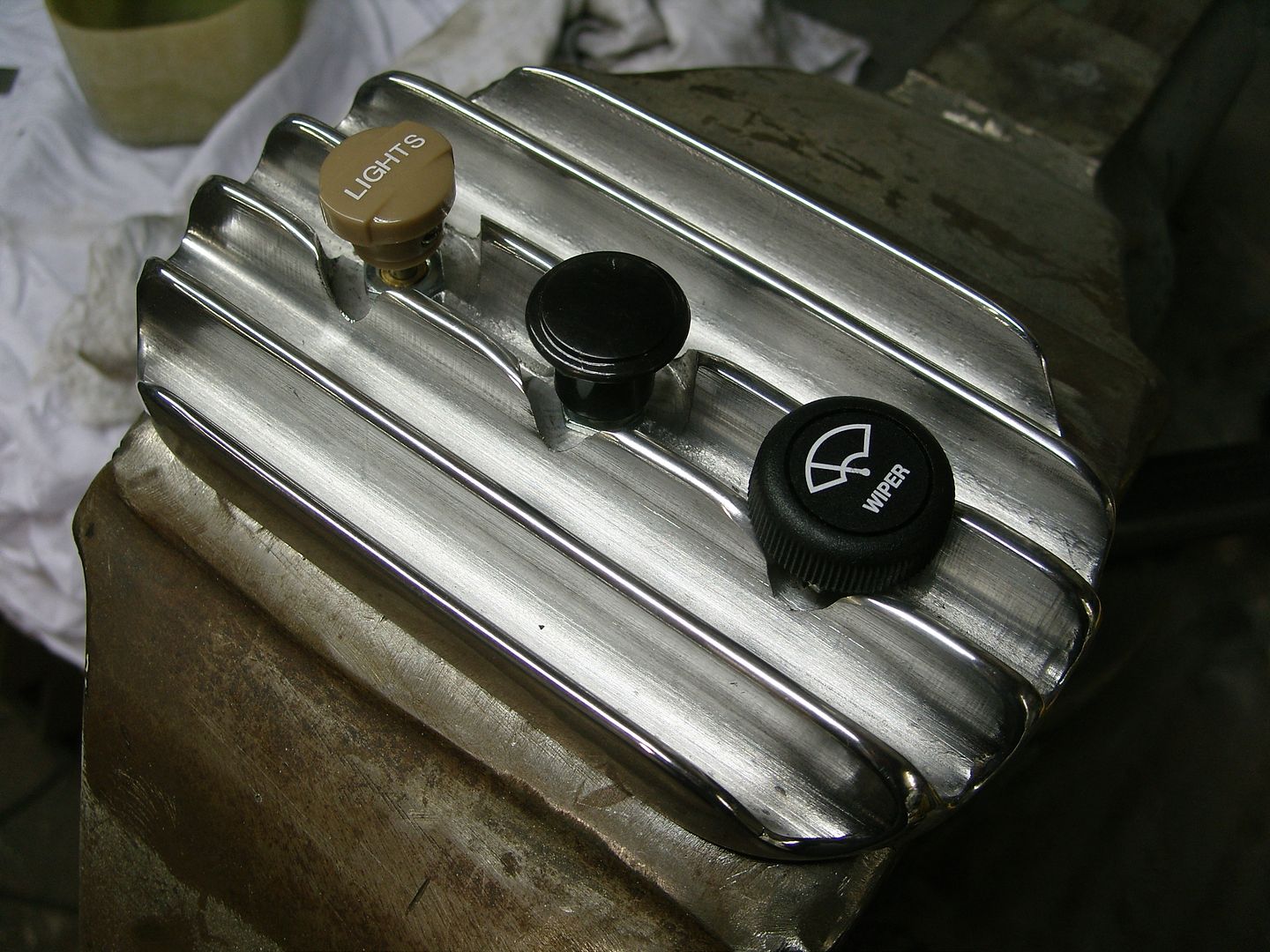
I was sat in the drivers seat the other night and realised i couldn't reach the dash when strapped in, I needed the important switches closer to me.
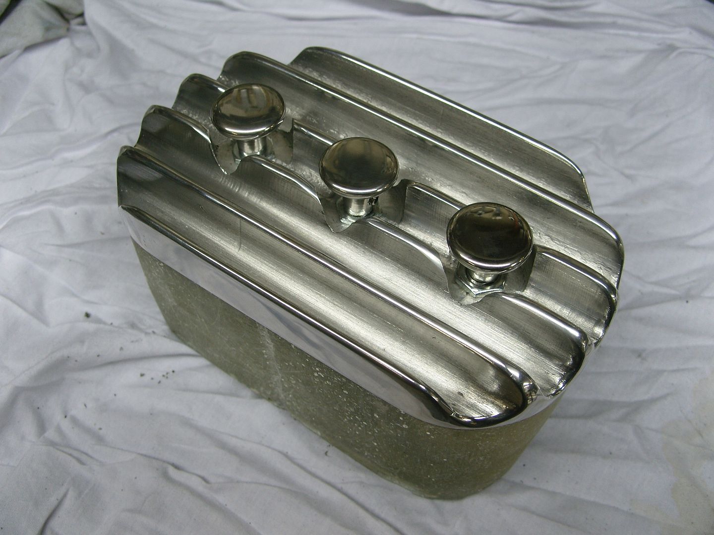
I solved this with a glassfibre box which was moulded off a washing sachet container.
I aim to mount this with some stainless tube between the seats and run the wiring through the tube so its hidden.
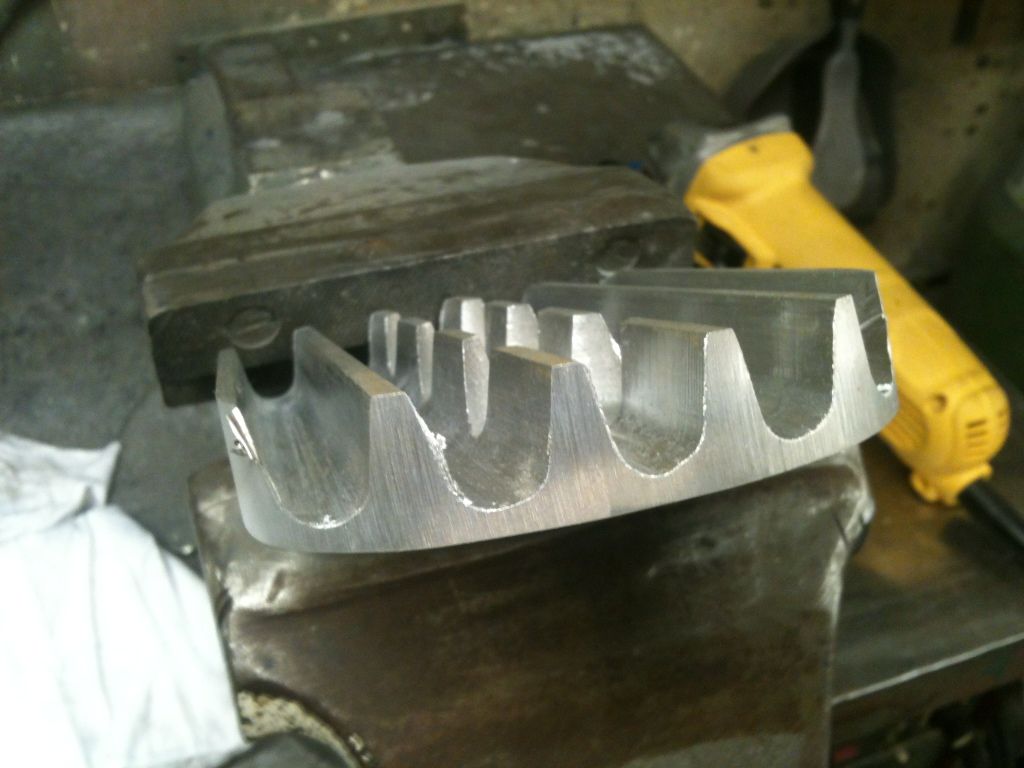
I thought a nice finned top plate to hold the switches might be nice, thickest bit of aluminium plate i had was 1/2" so a quick call to my mate Allan and he had some 3/4", He also kindly offered to mill the slots in it to save me some time.
First the 3/4" aluminium plate was cut.
Next it was marked out and drilled and counterbored.
Next the grooves were ball milled into the plate.
Next to get sloping sides on the fins the plate was tilted at 14 degrees and the sides of the fins got a pass with the cutter.
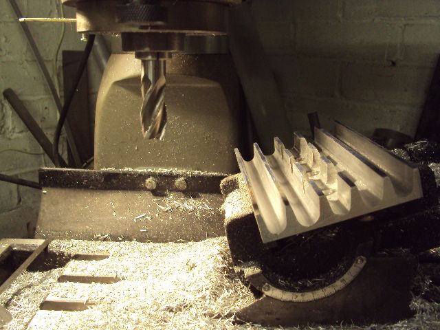
What we ended up with.
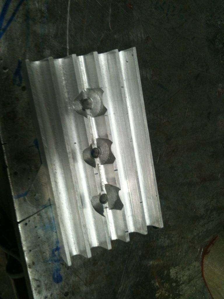
Next the shape was marked out and the excess cut off.
The ends of the fins were then curved.
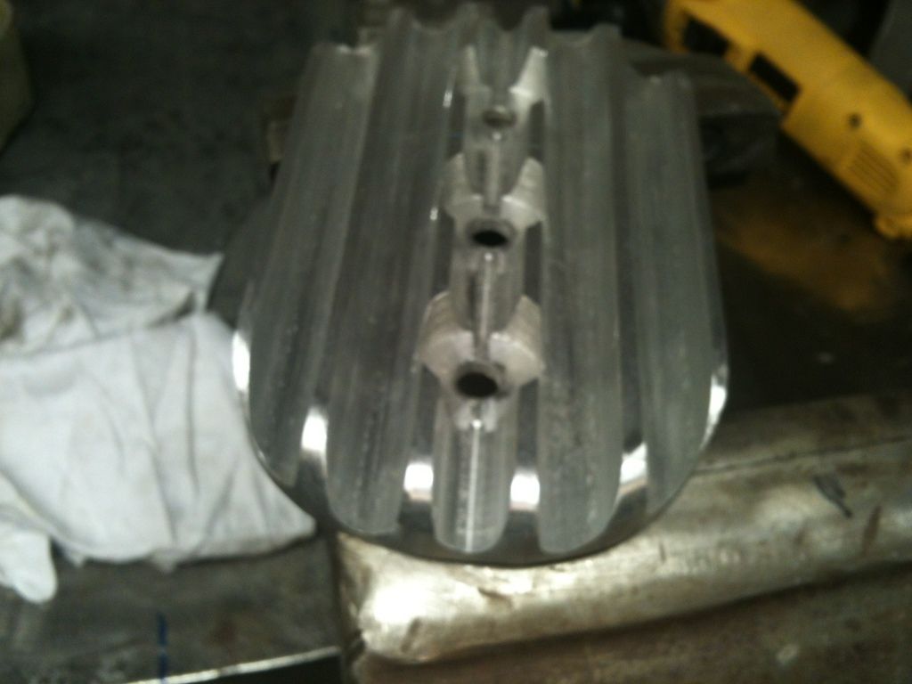
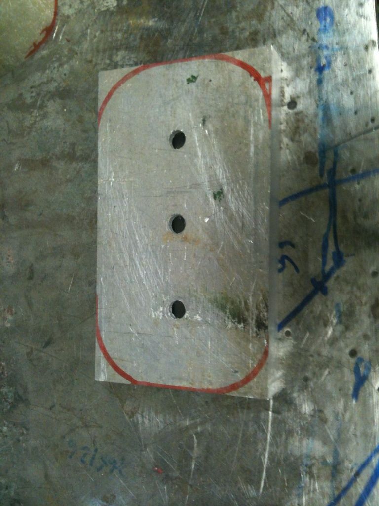
Next job was to remove all the sharp edges and replace with nice radius's and give it a quick polish to see how it looked.
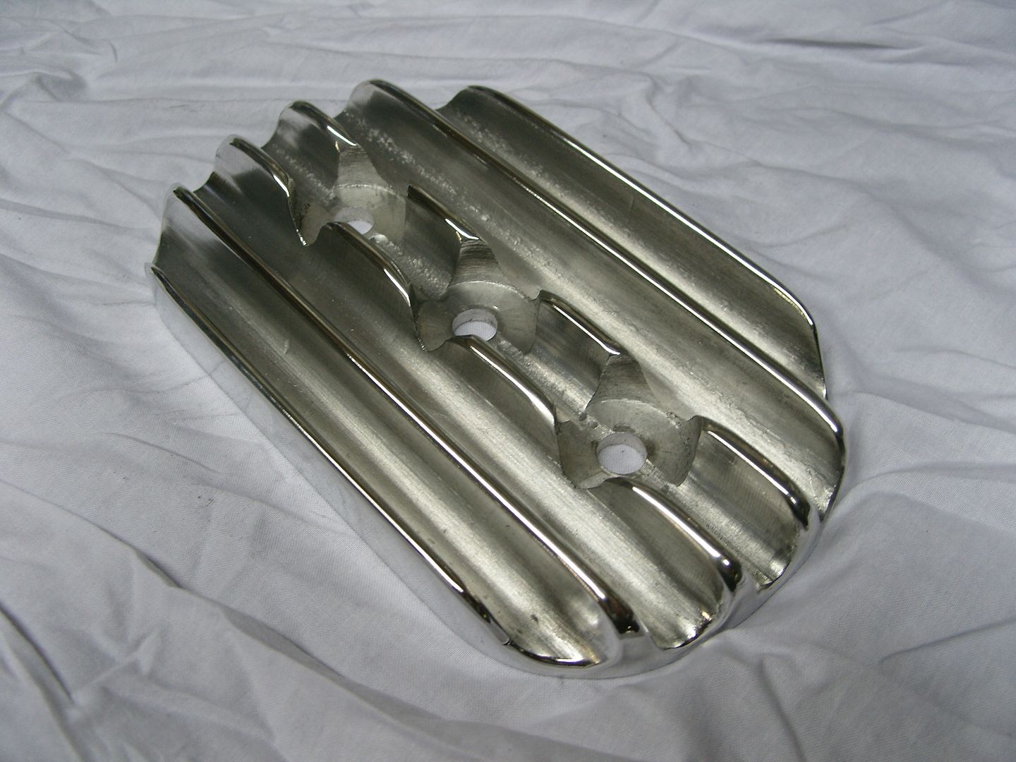
The original switch knobs were not gonna cut the mustard so new ones were made from some 1" stainless round bar.
:cheers:
I was sat in the drivers seat the other night and realised i couldn't reach the dash when strapped in, I needed the important switches closer to me.
I solved this with a glassfibre box which was moulded off a washing sachet container.
I aim to mount this with some stainless tube between the seats and run the wiring through the tube so its hidden.
I thought a nice finned top plate to hold the switches might be nice, thickest bit of aluminium plate i had was 1/2" so a quick call to my mate Allan and he had some 3/4", He also kindly offered to mill the slots in it to save me some time.
First the 3/4" aluminium plate was cut.
Next it was marked out and drilled and counterbored.
Next the grooves were ball milled into the plate.
Next to get sloping sides on the fins the plate was tilted at 14 degrees and the sides of the fins got a pass with the cutter.
What we ended up with.
Next the shape was marked out and the excess cut off.
The ends of the fins were then curved.
Next job was to remove all the sharp edges and replace with nice radius's and give it a quick polish to see how it looked.
The original switch knobs were not gonna cut the mustard so new ones were made from some 1" stainless round bar.
:cheers:
langy
langys rodshop
- Messages
- 6,095
- Location
- London
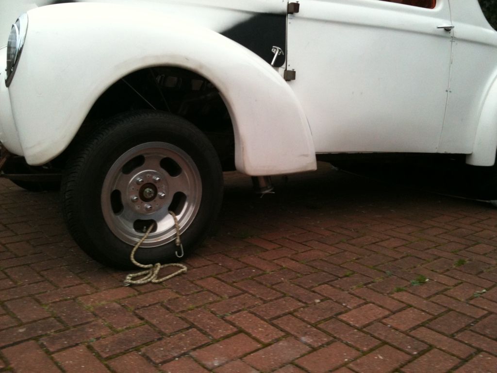
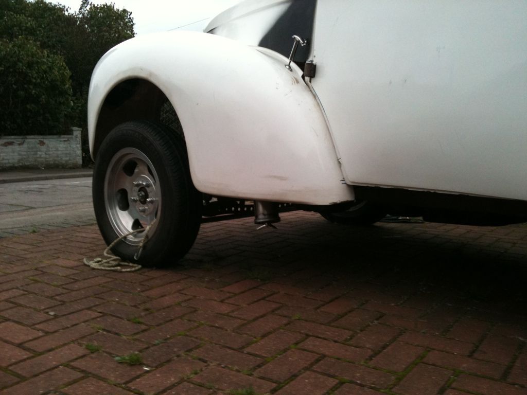
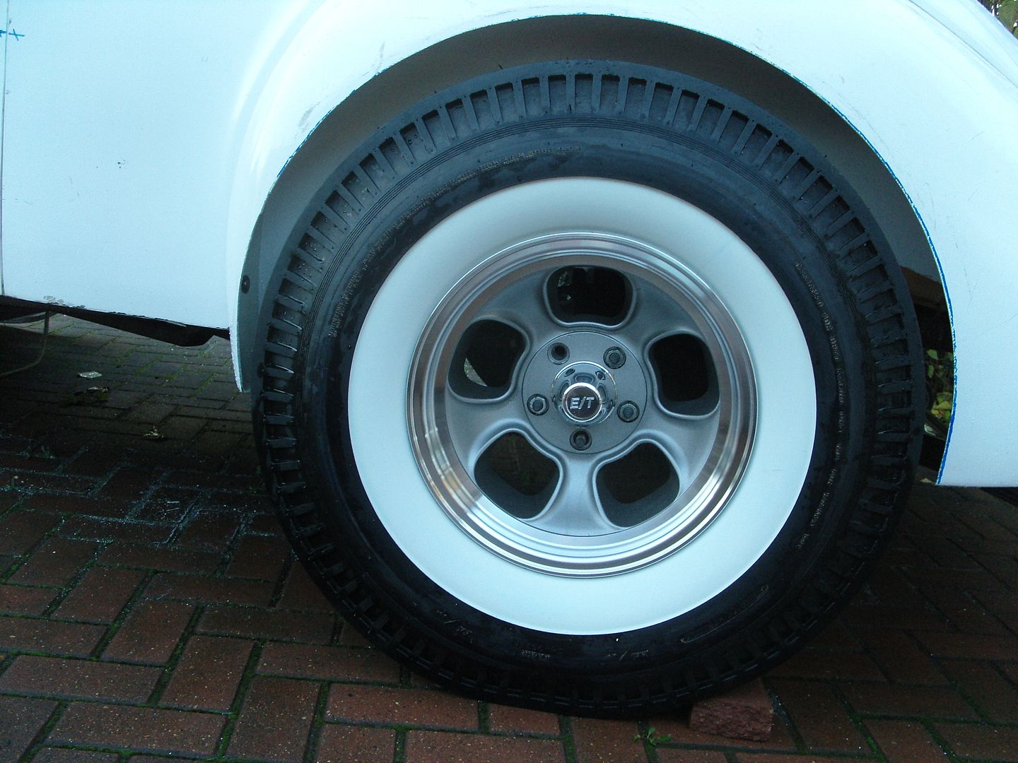
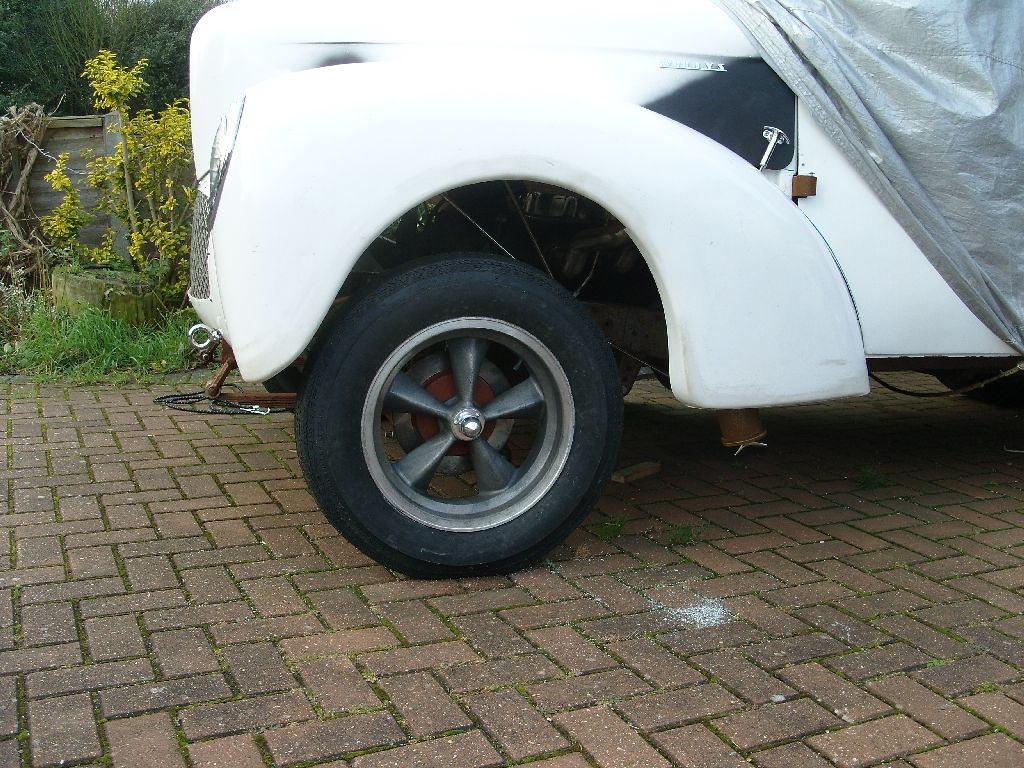
Had to go to the tyre place to get a customers tyres fitted and Crumble had got my tubes for me (thanks John) plus I had been itching to get my Radir tyres on my ET rims.
I had a slight clearence problem on the inner arch as these tyres bulge out a fair bit so I replaced the wheel studs with some longer Strange Eng studs and fitted a 1" spacer either side. I don't have a problem running spacers.
I'm still undecided about the whitewalls, I may turn them around.
Had to cut a fair bit out of the rear arches to get them on and they still need blending & fettling which i will sort at bodywork time. Its got a bit more attitude now.
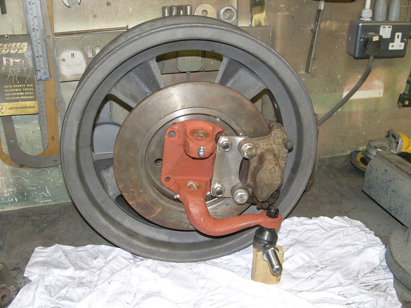
Met Carl at Heathrow to pickup my front wheels, Carl had already started on the disc conversion but not finished it so i have a little machining left to do.
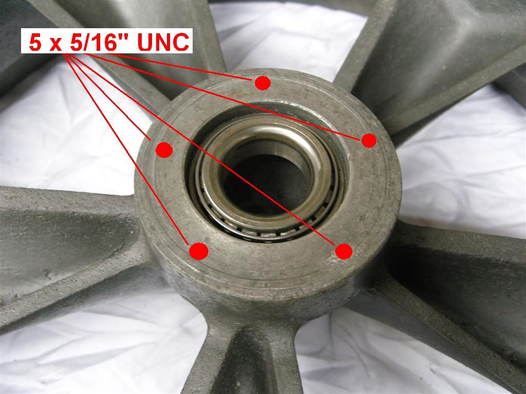
The disc is positioned on the wheel hub by an adaptor that also holds the oil seal. 5 holes need to be drilled through the disc, adaptor and into the wheel hub, these will be slightly counterbored and tapped 5/16" UNC, a coarse thread is used as the magnesium is very soft and i fine thread could possibly strip, the studs are fitted into the counterbore so that the force is taken by the shank of the ARP studs I am using and not the threaded section.
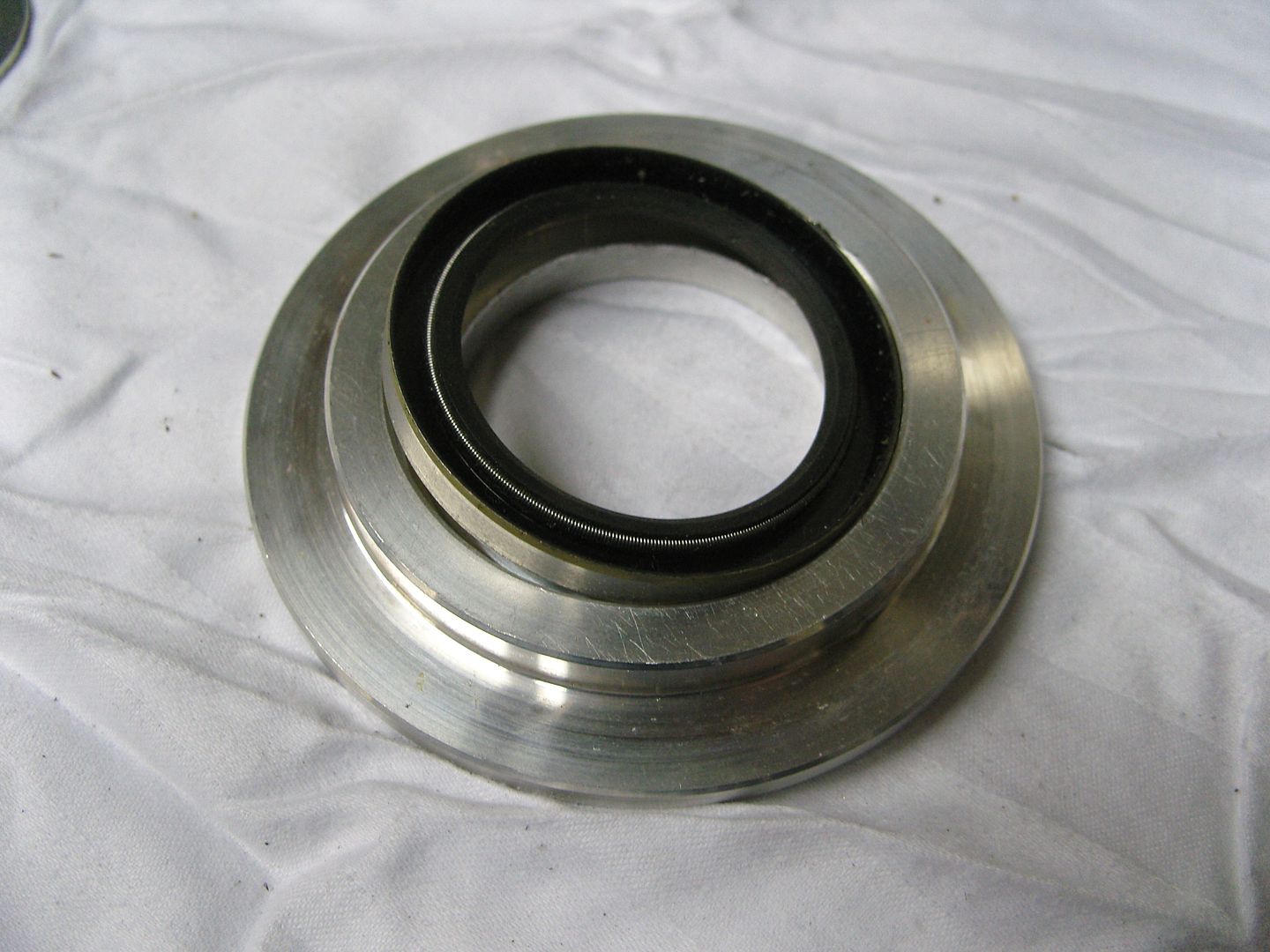
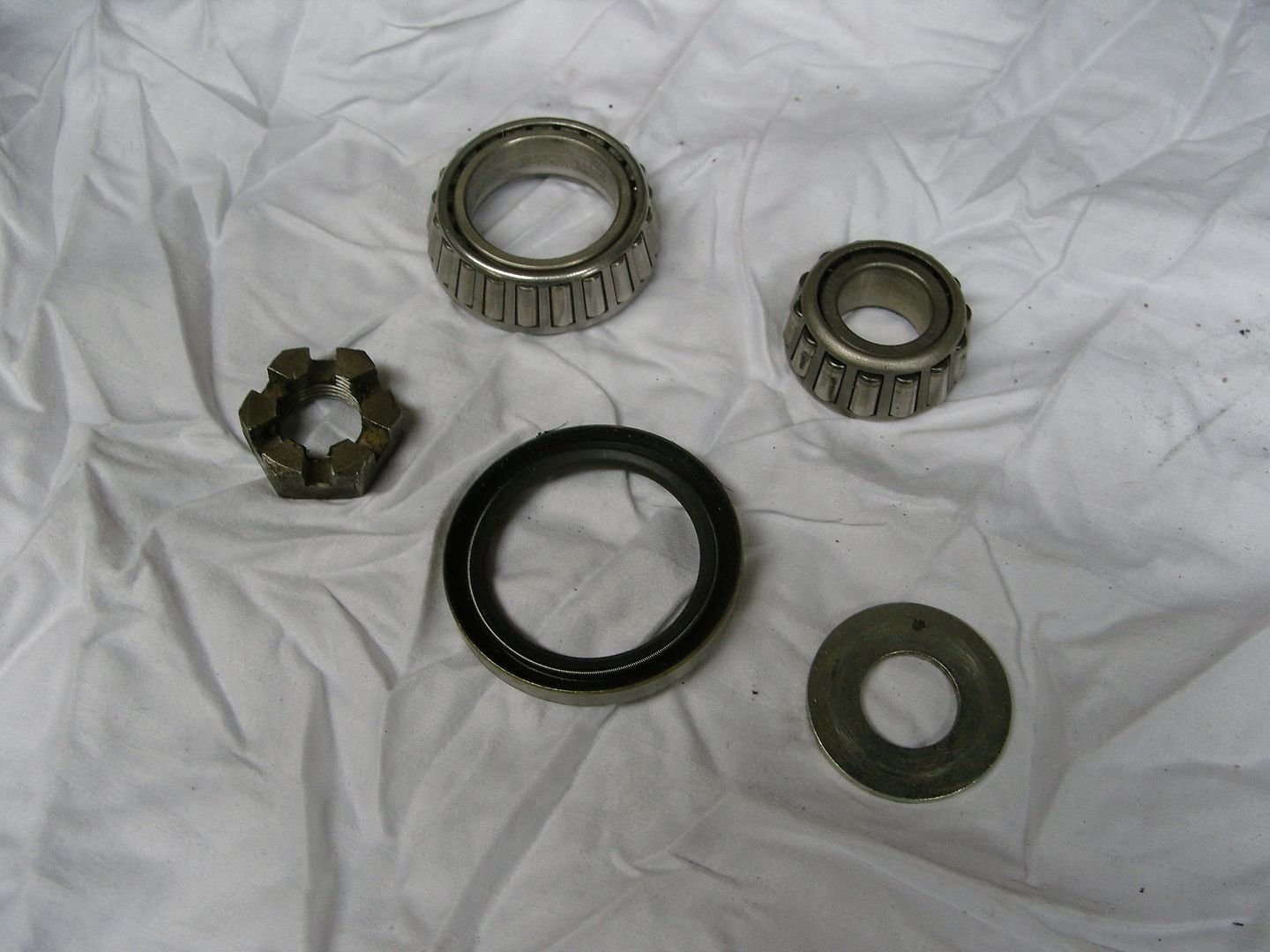
The spindle is an early ford part & bearing setup is normal taper bearings with a standard size oil seal.
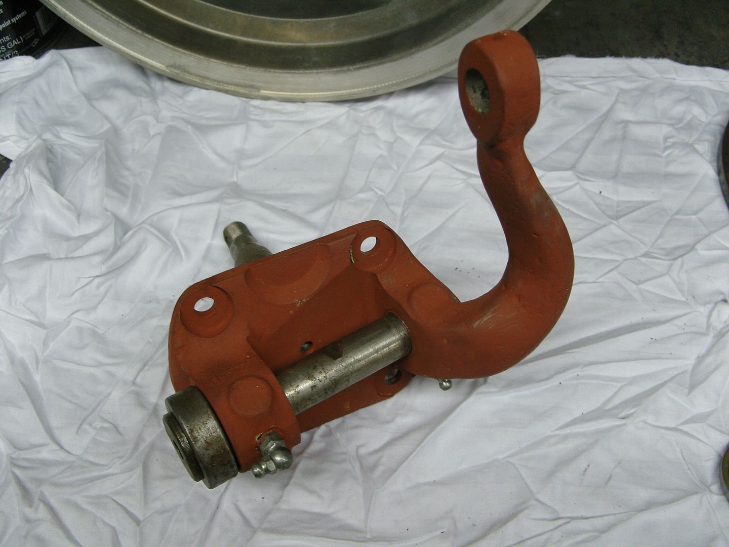
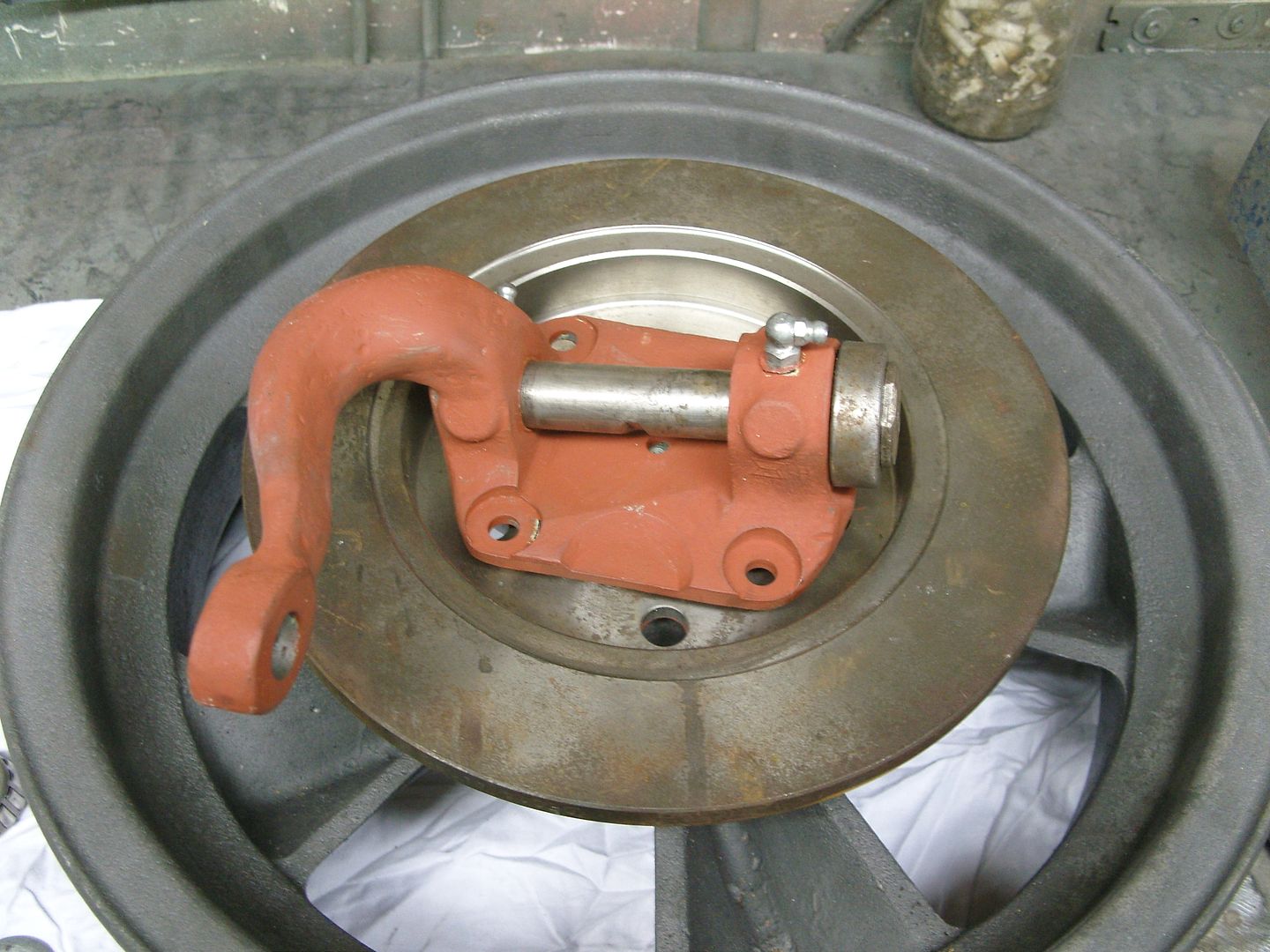
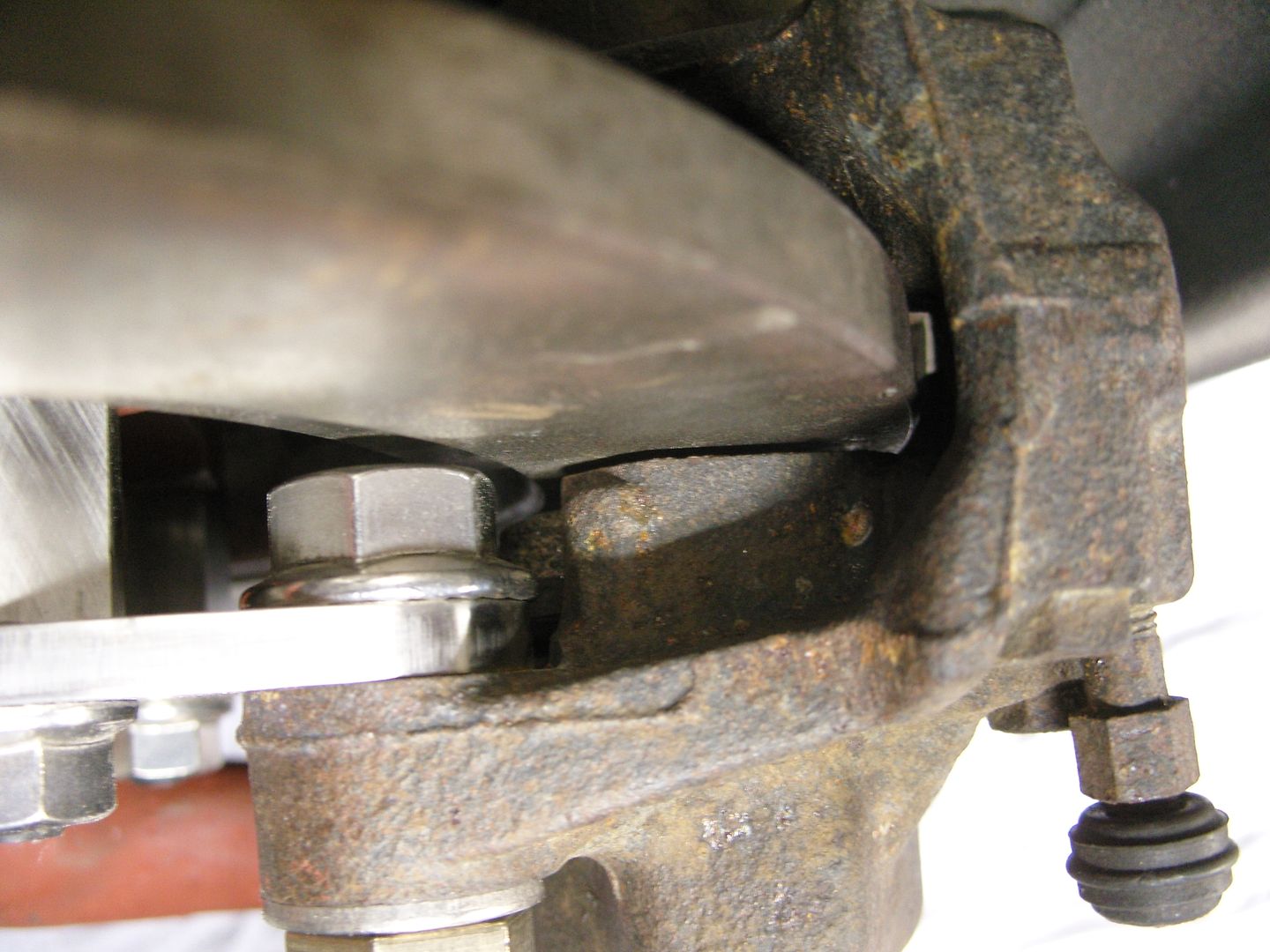
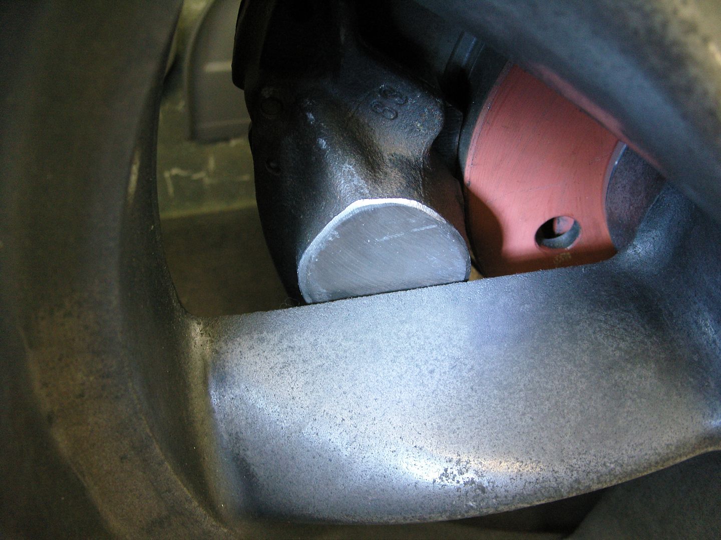
The calipers & disc is from a modern car and the caliper has to be fairly small to clear the wheel, clearences are very tight !!!
Custom caliper brackets have to be made and removing a wheel means removing a caliper first so this has to be taken into account when making the brackets. 3/8" UNF hi tensile bolts hold the spindle to the internally threaded hexagon bar caliper spacers.
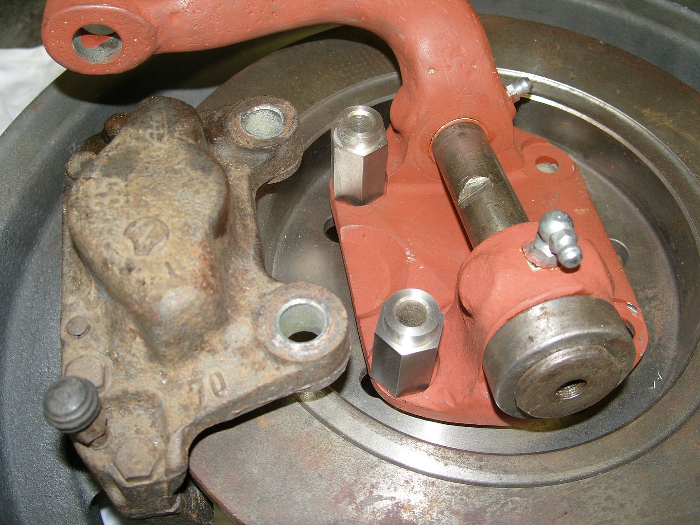
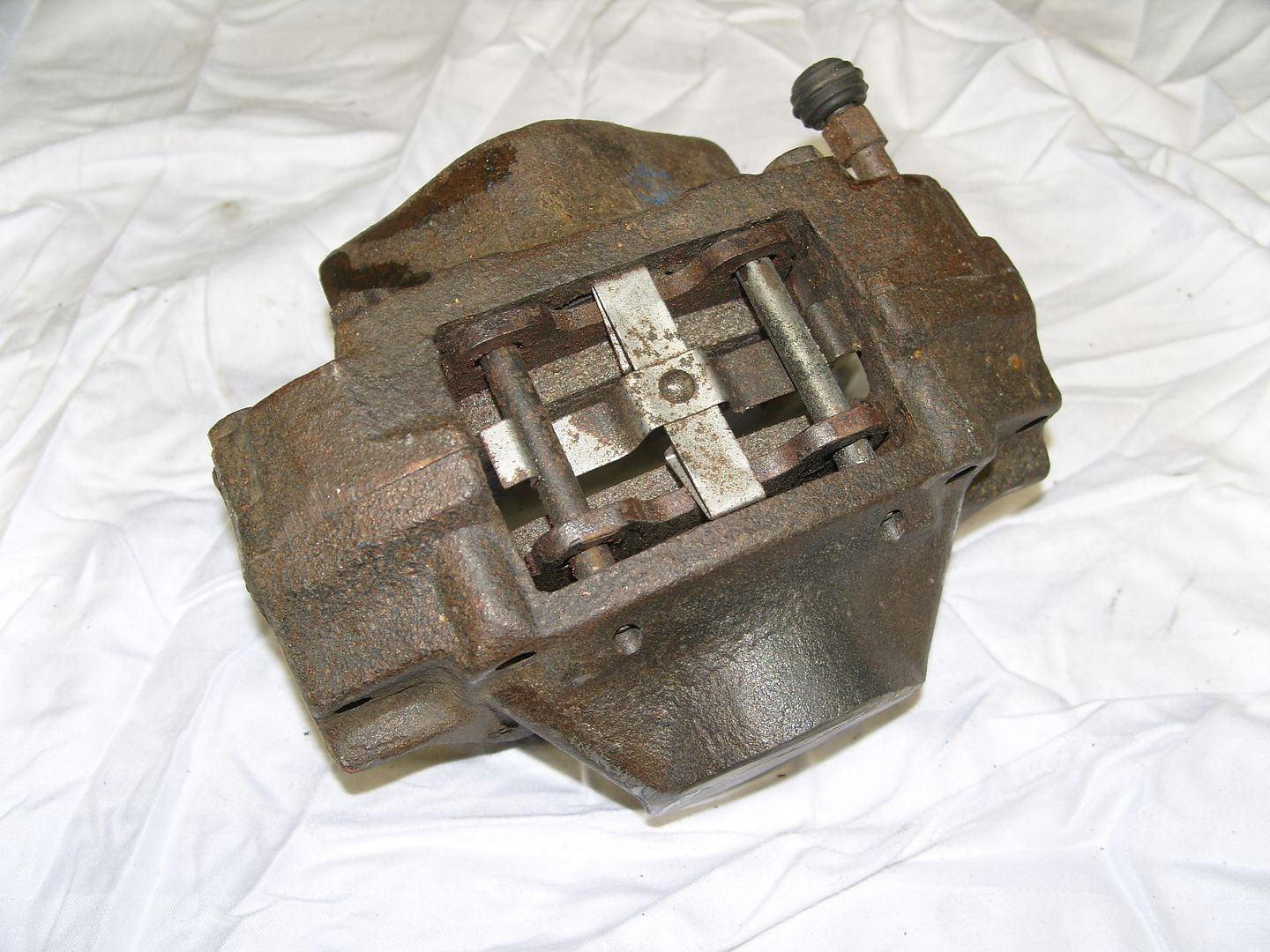
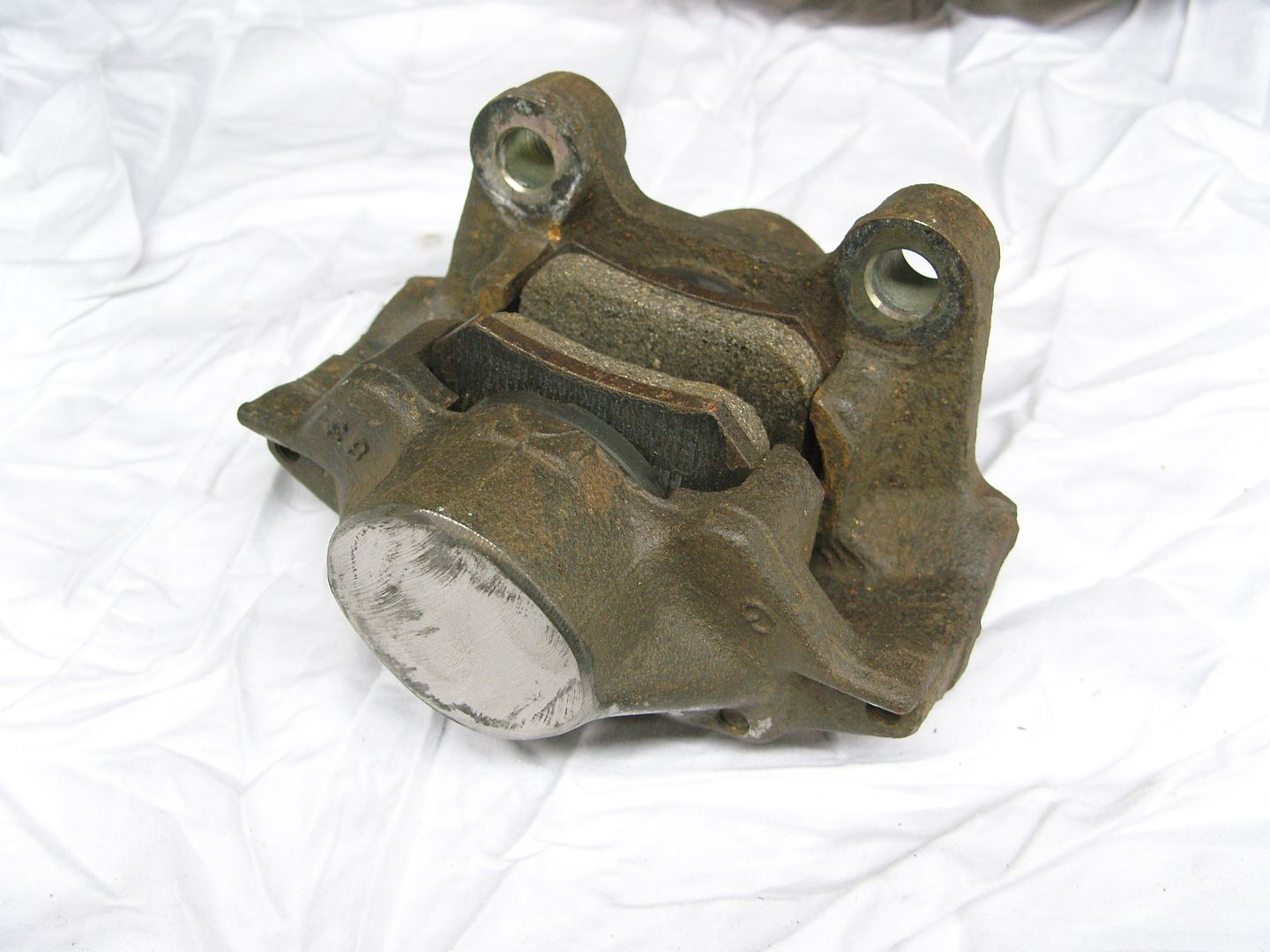
The caliper plates are made in 1/4" stainless plate, Securing bolts are hi tensile countersunk setscrews that have been modified slightly.
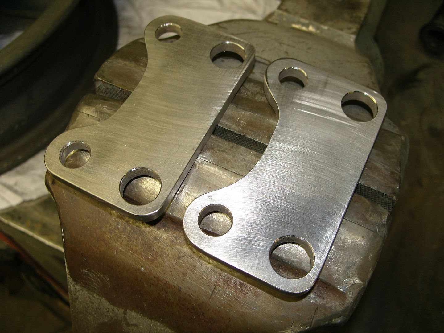
Heres the completed setup.
.
.
I had a slight clearence problem on the inner arch as these tyres bulge out a fair bit so I replaced the wheel studs with some longer Strange Eng studs and fitted a 1" spacer either side. I don't have a problem running spacers.
I'm still undecided about the whitewalls, I may turn them around.
Had to cut a fair bit out of the rear arches to get them on and they still need blending & fettling which i will sort at bodywork time. Its got a bit more attitude now.
Met Carl at Heathrow to pickup my front wheels, Carl had already started on the disc conversion but not finished it so i have a little machining left to do.
The disc is positioned on the wheel hub by an adaptor that also holds the oil seal. 5 holes need to be drilled through the disc, adaptor and into the wheel hub, these will be slightly counterbored and tapped 5/16" UNC, a coarse thread is used as the magnesium is very soft and i fine thread could possibly strip, the studs are fitted into the counterbore so that the force is taken by the shank of the ARP studs I am using and not the threaded section.
The spindle is an early ford part & bearing setup is normal taper bearings with a standard size oil seal.
The calipers & disc is from a modern car and the caliper has to be fairly small to clear the wheel, clearences are very tight !!!
Custom caliper brackets have to be made and removing a wheel means removing a caliper first so this has to be taken into account when making the brackets. 3/8" UNF hi tensile bolts hold the spindle to the internally threaded hexagon bar caliper spacers.
The caliper plates are made in 1/4" stainless plate, Securing bolts are hi tensile countersunk setscrews that have been modified slightly.
Heres the completed setup.
.
.
langy
langys rodshop
- Messages
- 6,095
- Location
- London
Clearances are a little on the tight side !!!
.
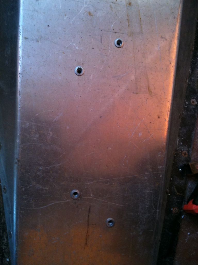
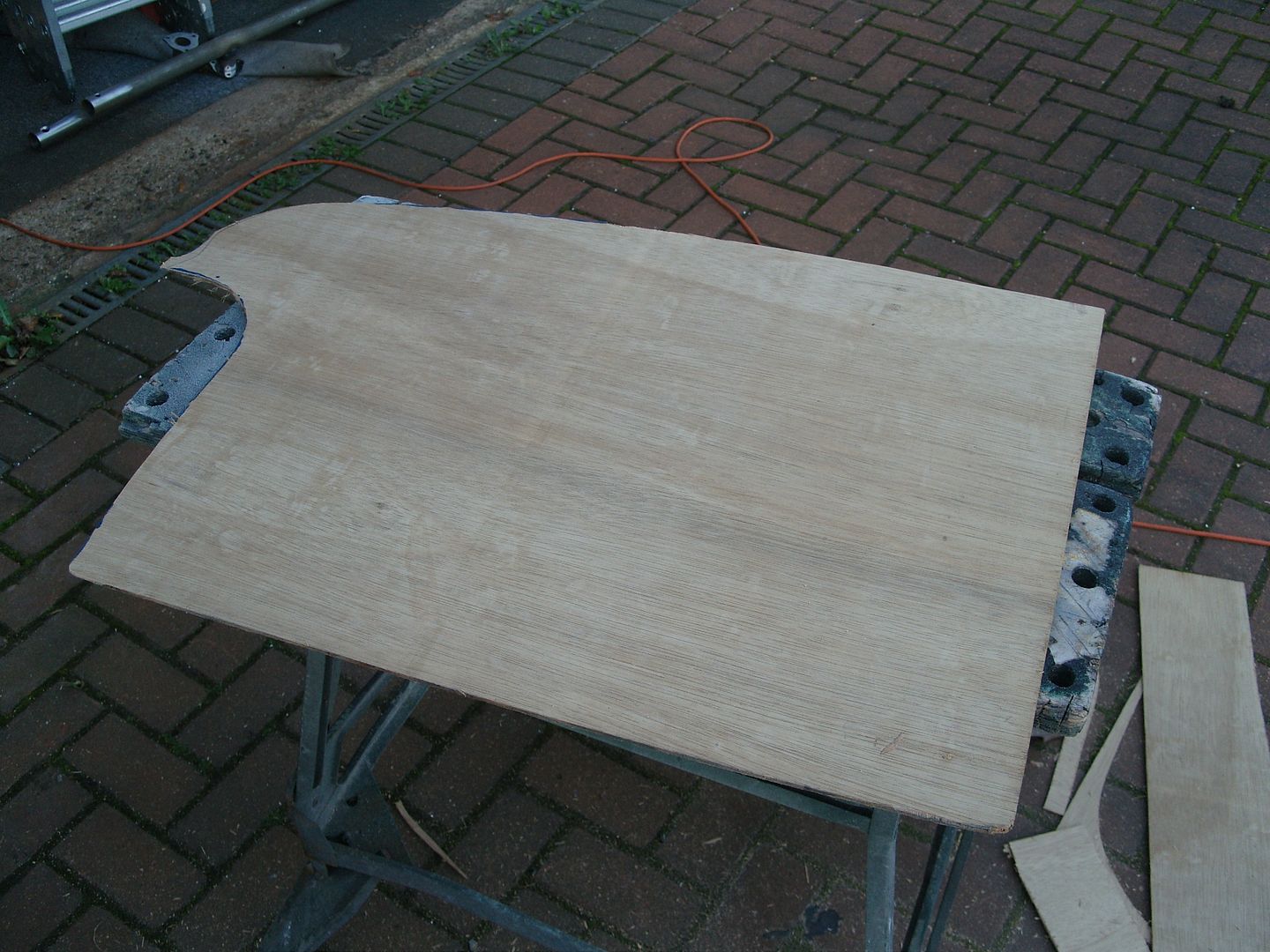
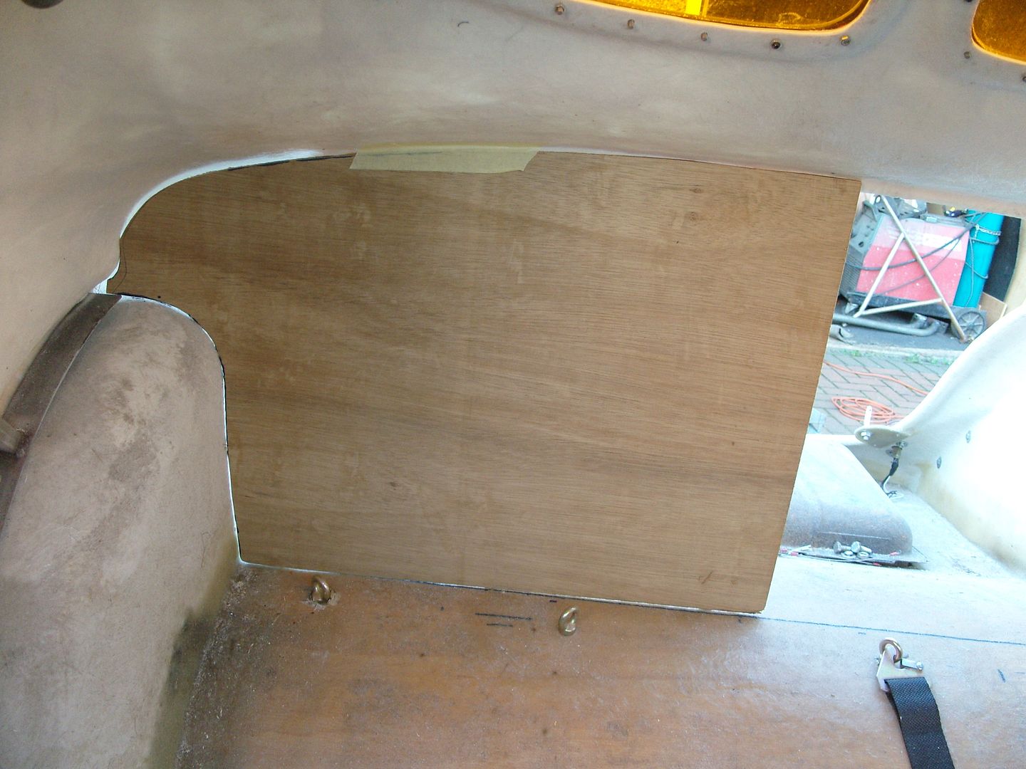
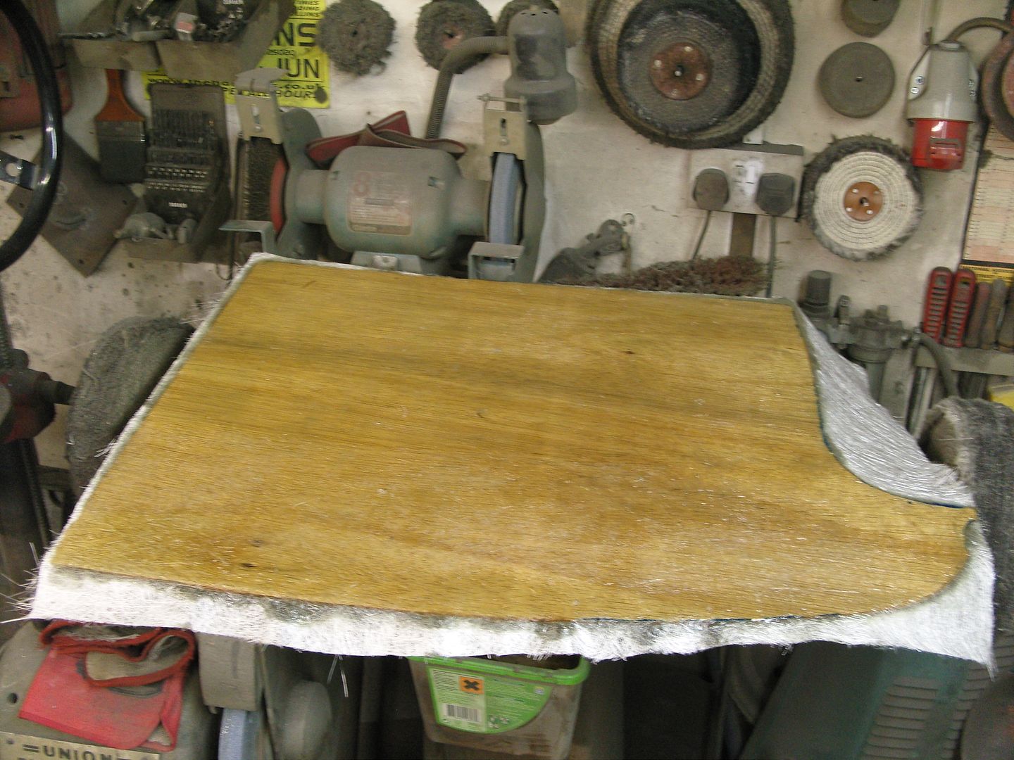
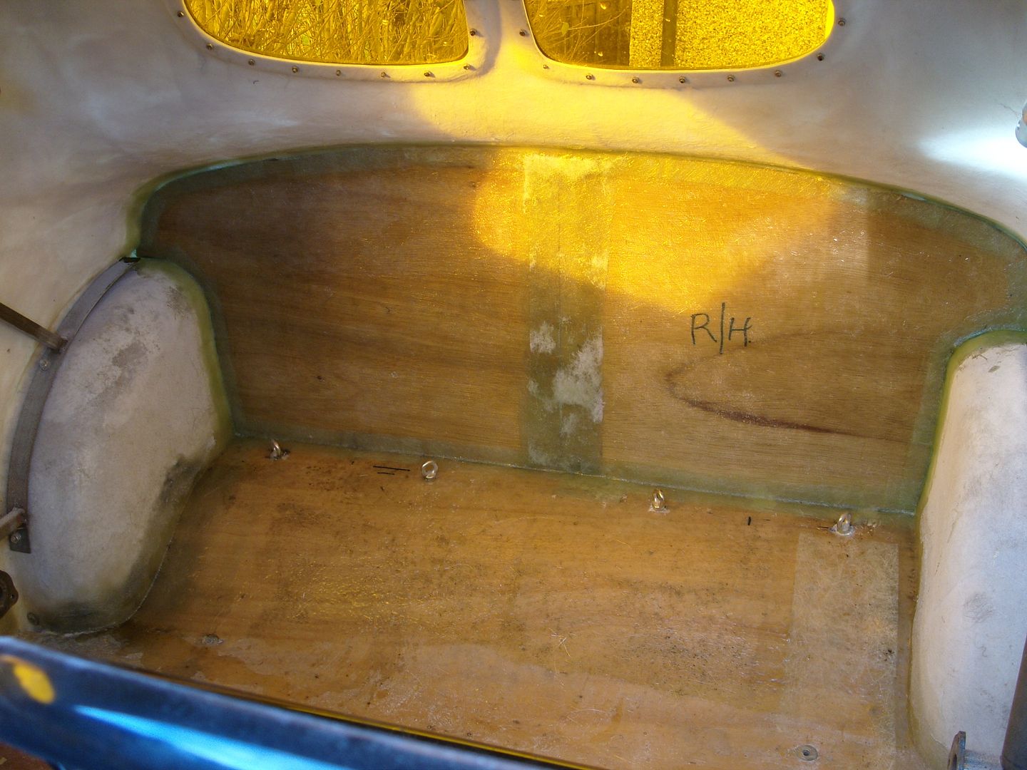
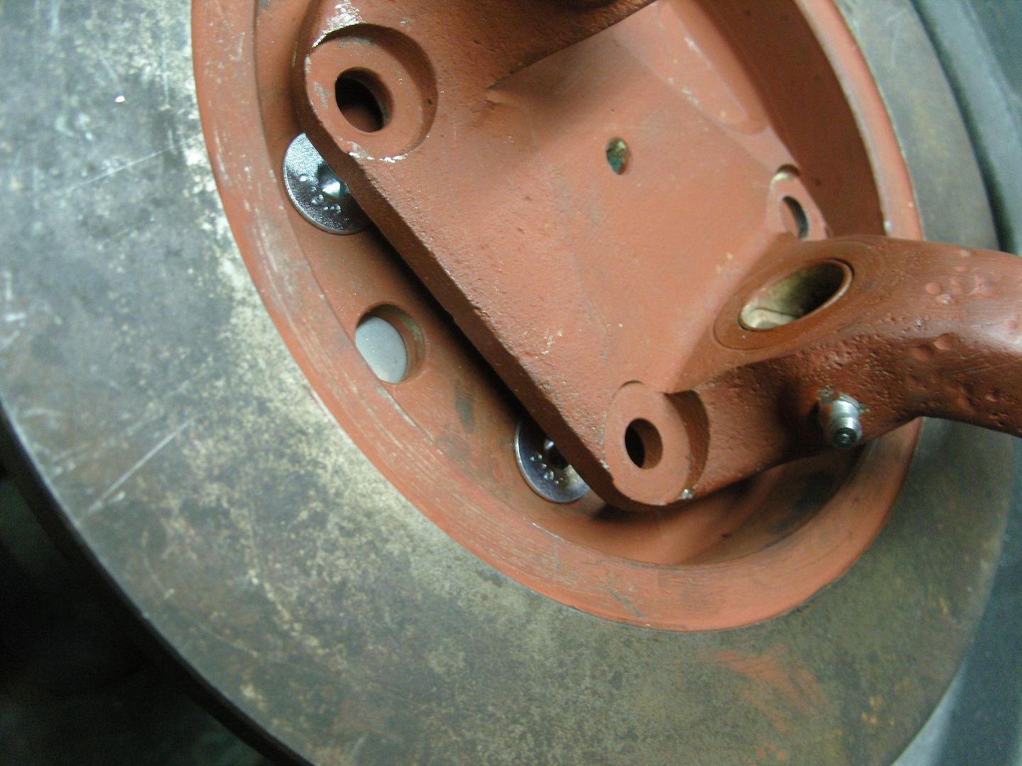
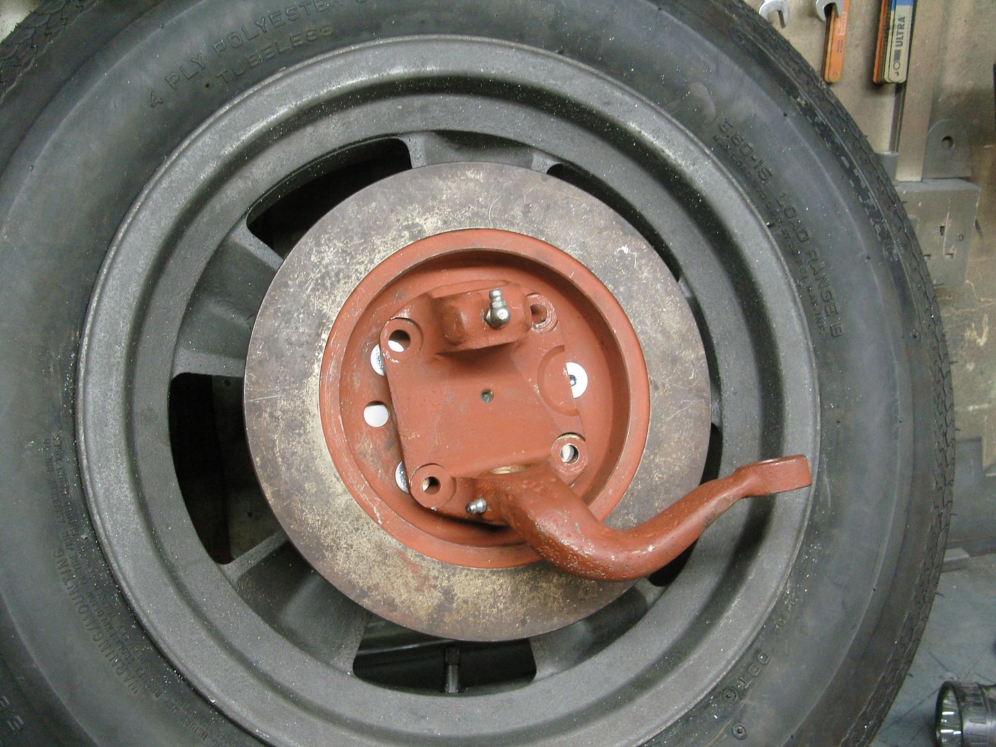
Not much happening as winter is now upon us but i did have to put in a firewall behind the seats, was going to use aluminium sheet but decided using 3mm ply was easier and once it had some glass & resin on it it would stiffen up.
Did it in 2 pieces for speed and ease.
Heres the opening to block off
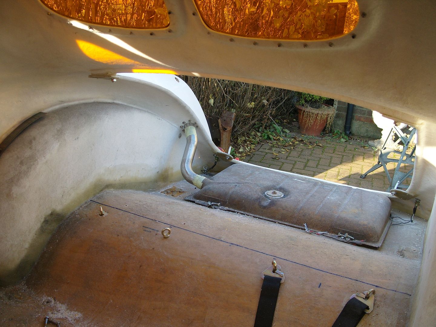
First a template was cut and tried for fit.
Next a layer of glass mat was applied to each side.
All glassed in place, like a steel panel now.
Also got my battery box made up & fitted.
Also when i went to the chrome shop this week some of my cage/seat mounts had been done, He is doing it in between jobs so hopefully the rest will be done next week.
.
Not much happening as winter is now upon us but i did have to put in a firewall behind the seats, was going to use aluminium sheet but decided using 3mm ply was easier and once it had some glass & resin on it it would stiffen up.
Did it in 2 pieces for speed and ease.
Heres the opening to block off
First a template was cut and tried for fit.
Next a layer of glass mat was applied to each side.
All glassed in place, like a steel panel now.
Also got my battery box made up & fitted.
Also when i went to the chrome shop this week some of my cage/seat mounts had been done, He is doing it in between jobs so hopefully the rest will be done next week.
langy
langys rodshop
- Messages
- 6,095
- Location
- London
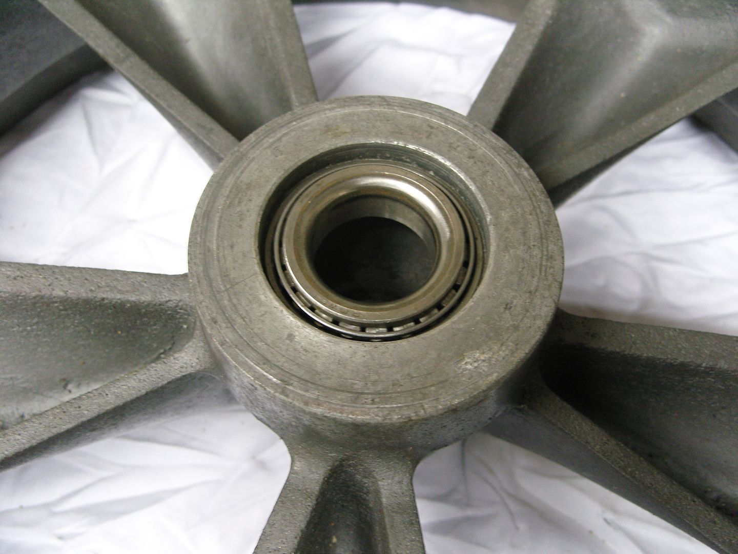
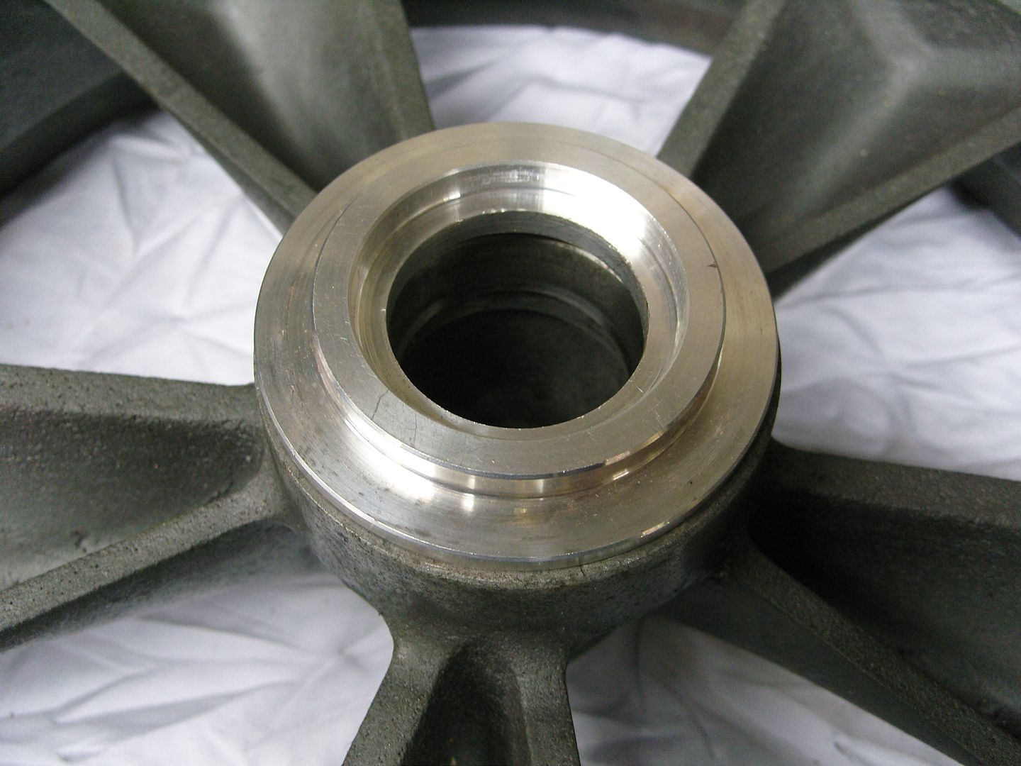
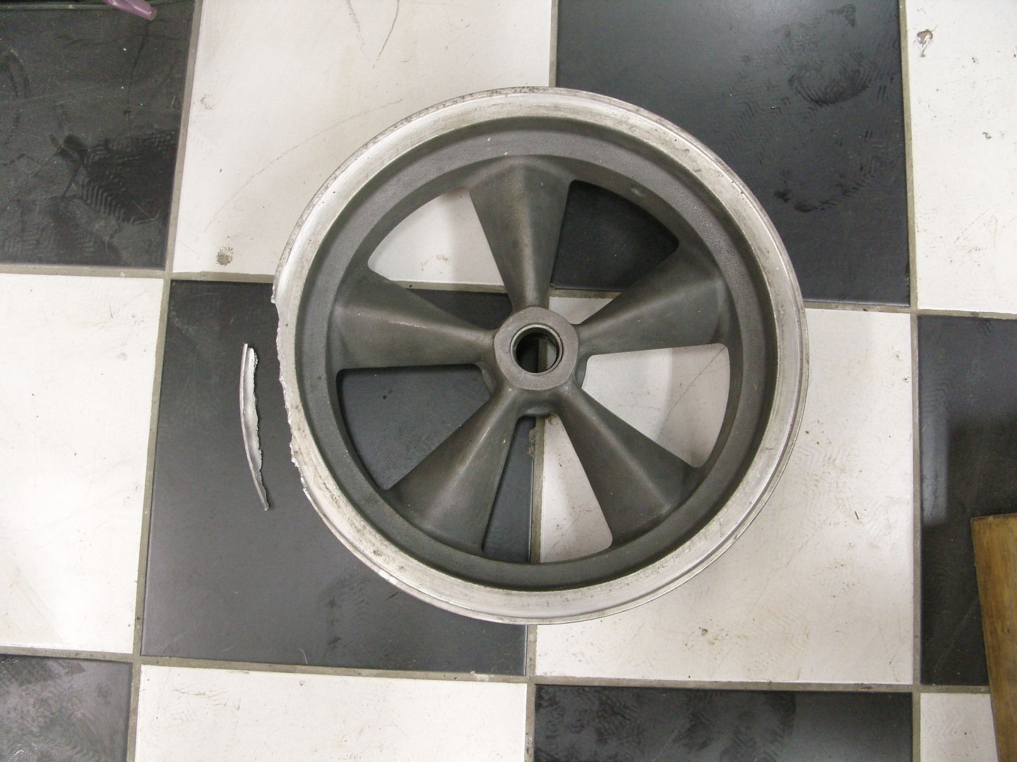
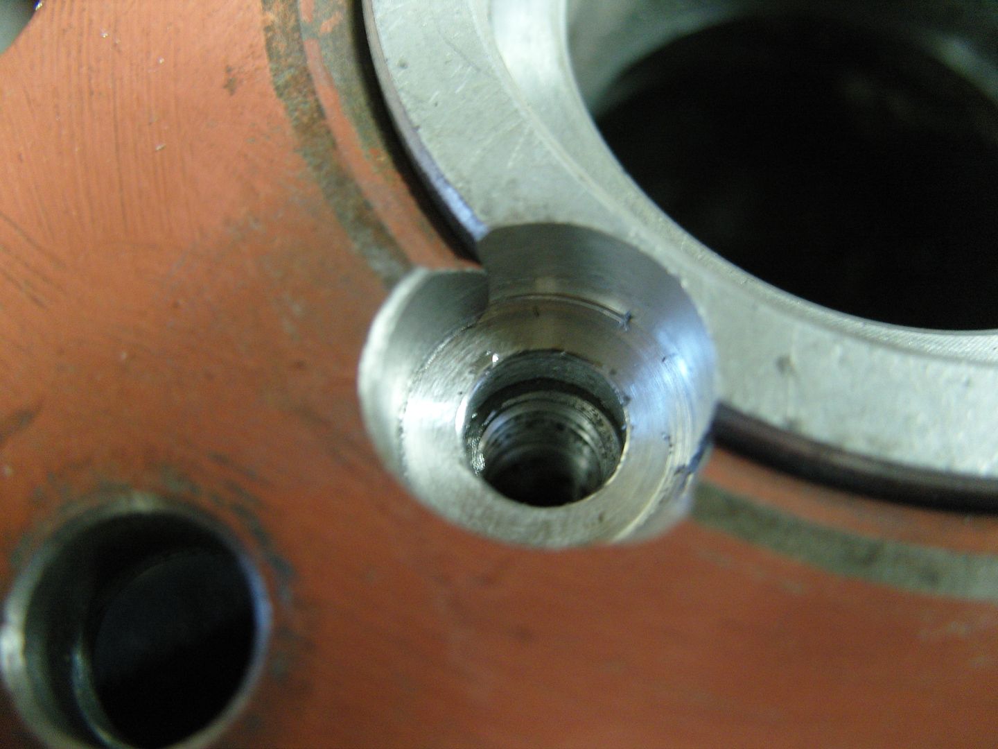
I gave my Mags to a machinist as the plan has changed slightly and i needed more accuracy than the old bridgeport i use has, I needed to come up with a pair of grease retaining caps for the outside of the hub so i spun a pair up in the lathe from 2.5" aluminium bar.
Firstly i bored out the shape and then turned the outside shape into the bar, then the outside was sanded to a nice radius.
The first one came out perfect
But i screwed up on the second one by taking off to much material, these are only 1/16" thick so it was easily done :eek:
I always say everybody screws up occassionaly but the important thing is how you rescue the situation and save the day by not having to remake another !!!
Welding was my first thought, Now i don't do much aluminium welding and certainly not on something this thin !!! Anyway popped over to see my mate Gary and we decided to have a go at it, as soon as the TIG sparked up it blew a hole so it was decided to run 2 beads 1/4" apart with 1.6mm rod and then fill in the gap between with 3mm rod, It worked a treat although doesn't look pretty !!!
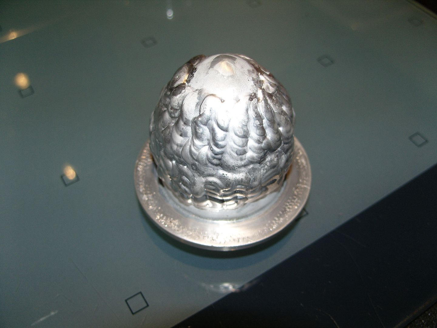
Back at the workshop it went back in the lathe and the inside was rebored and cleaned out, then the outside was recontoured and sanded. A liner was made to be a slide fit inside so it could be gripped securley in the chuck.
A quick wipe up on the polisher and the job was done, 3 equidistant holes were drilled for machne screws that secure it to the wheel hub.
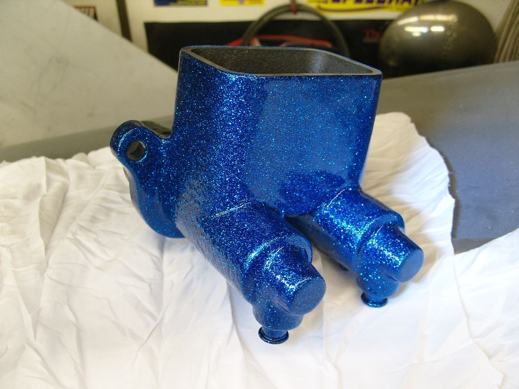
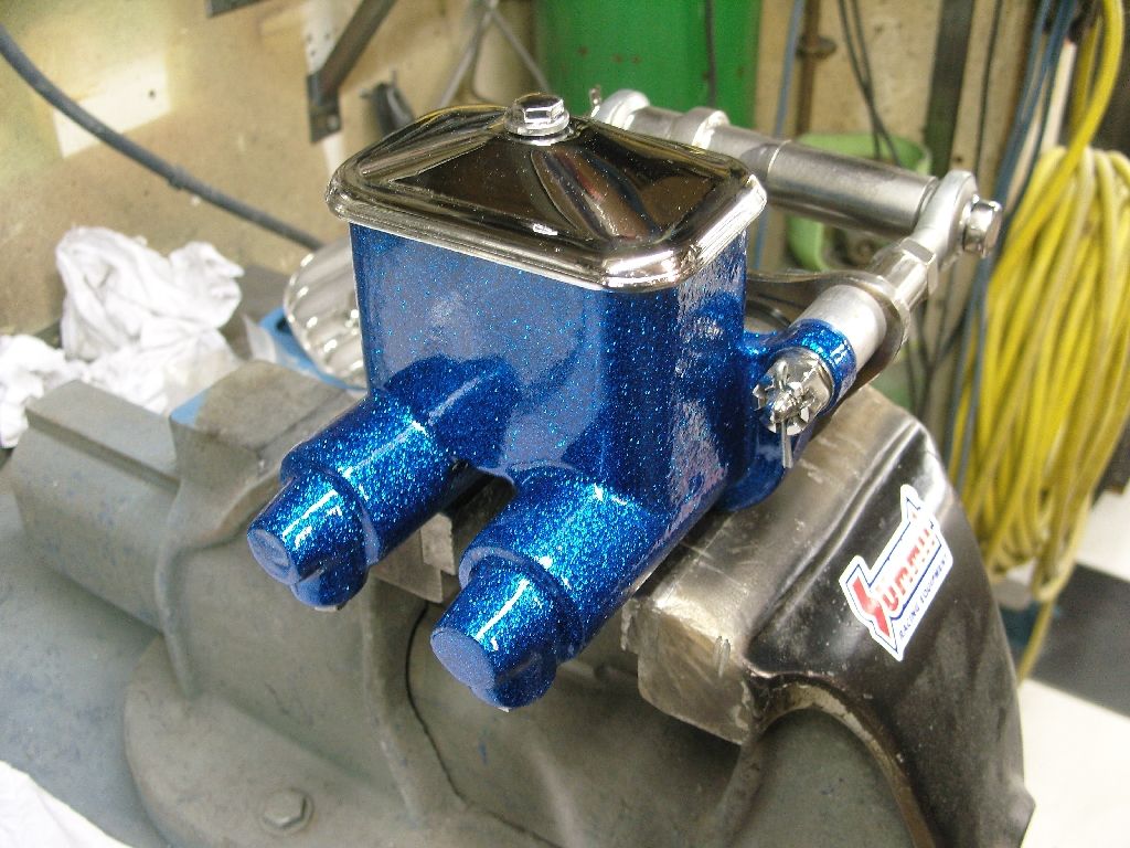
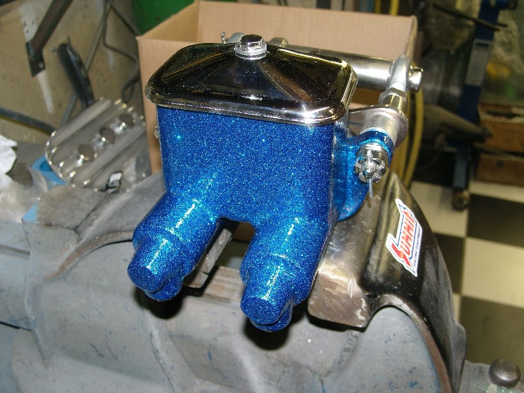
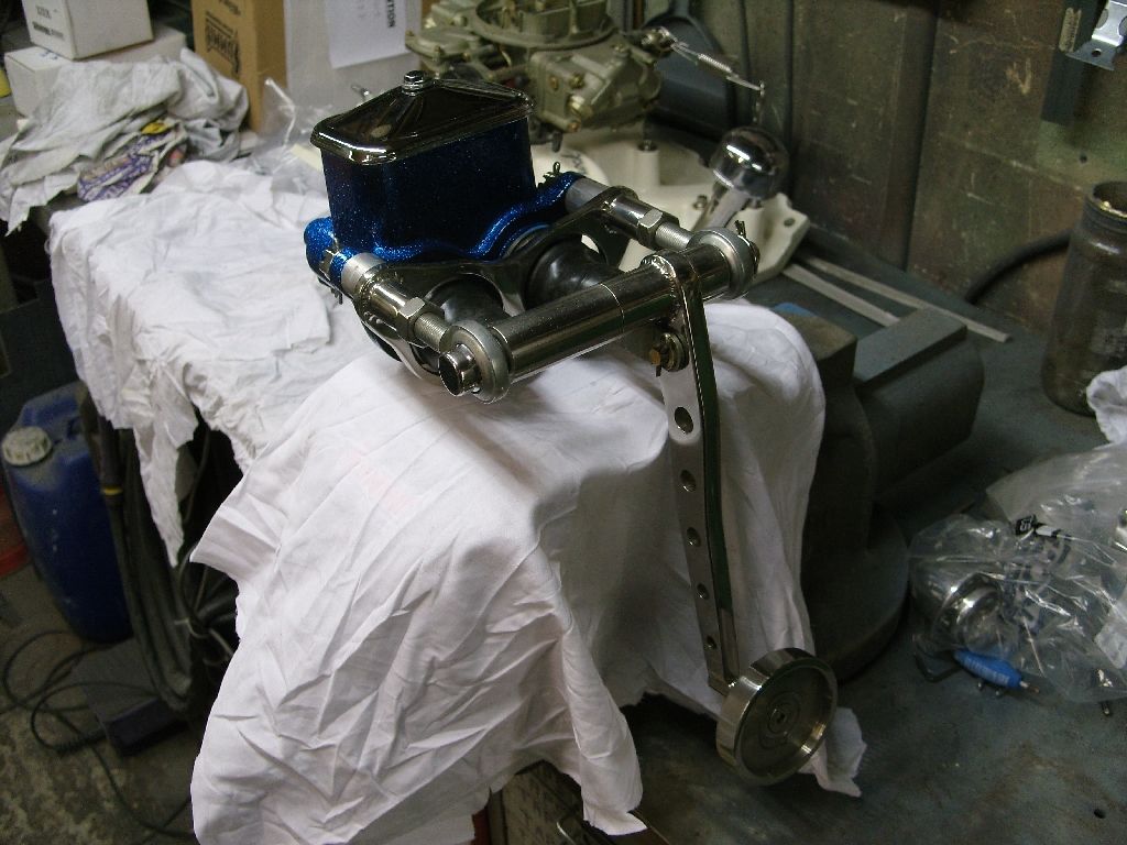
Had to paint some kitchen cabinet doors today so thought while i had the gun out i would do a test piece to see what my Blue flake was going to look like.
I chose the master cylinder as I had already smoothed it out a bit.
First up i gave it a couple of coats of Epoxy primer
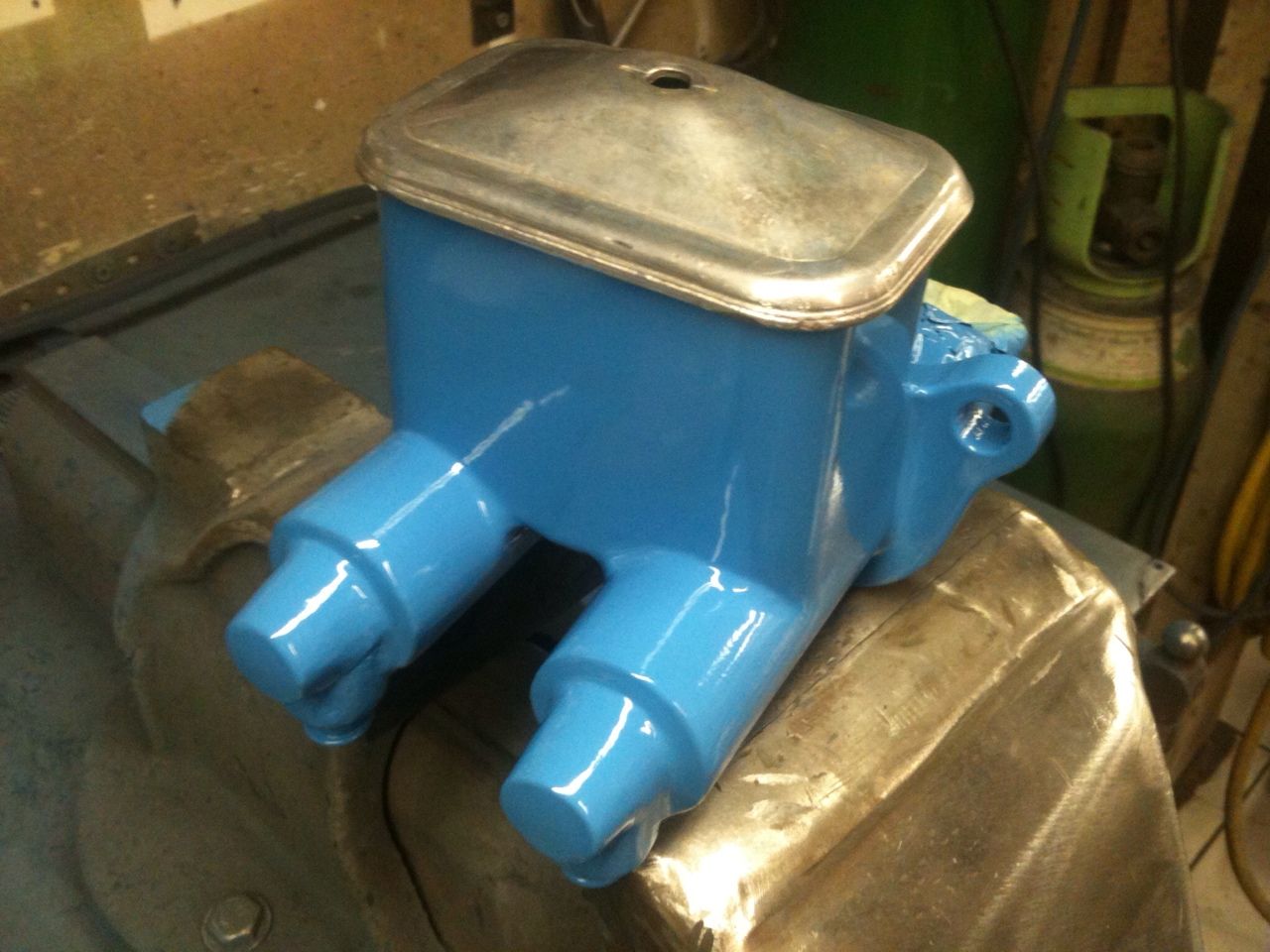
After it had dried it got a quick key up with 600 wet and a coat of Black epoxy on it, I've decided to use a Black basecoat this time as it will save me a lot of work when i paint the body, I can primer it in Black and then go straight on with the blue flake therefore saving money on bascoat and time.
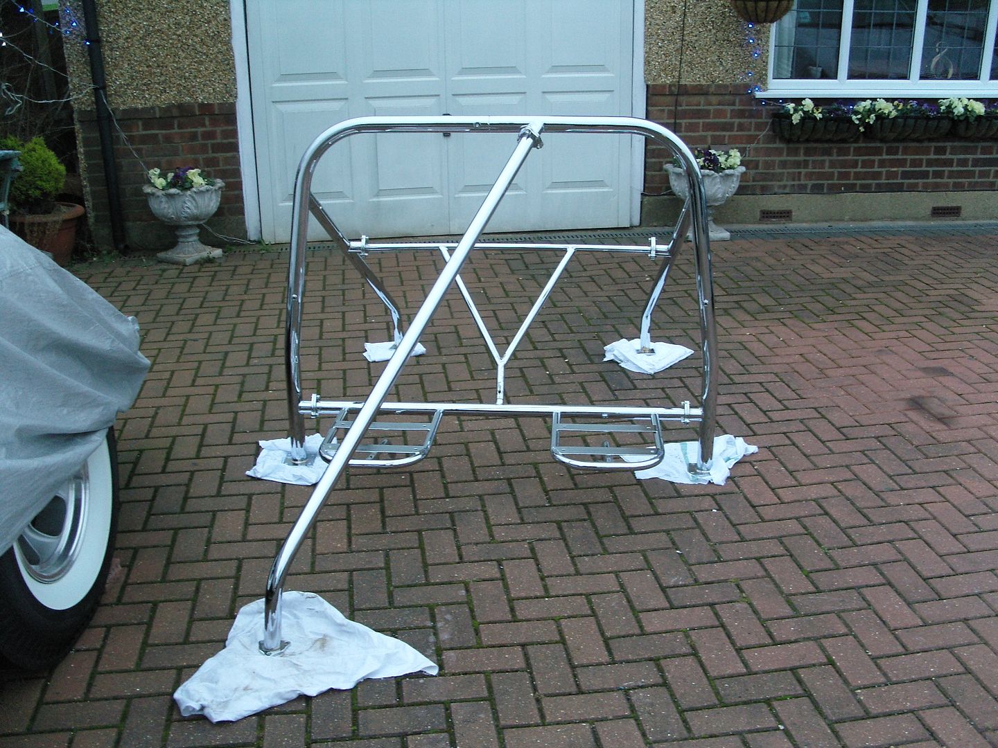
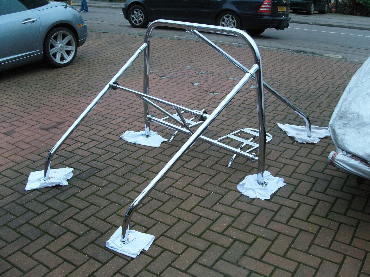
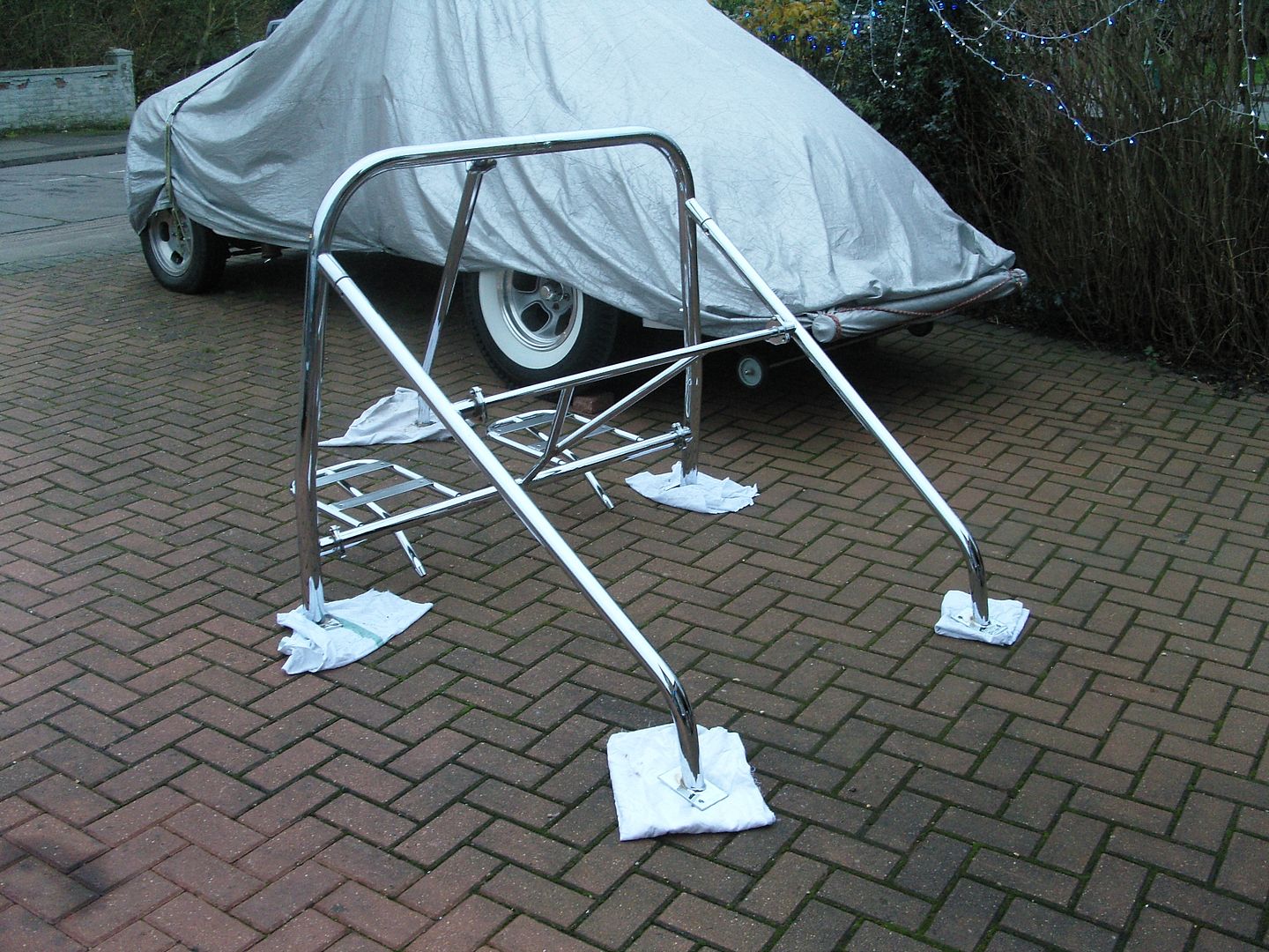
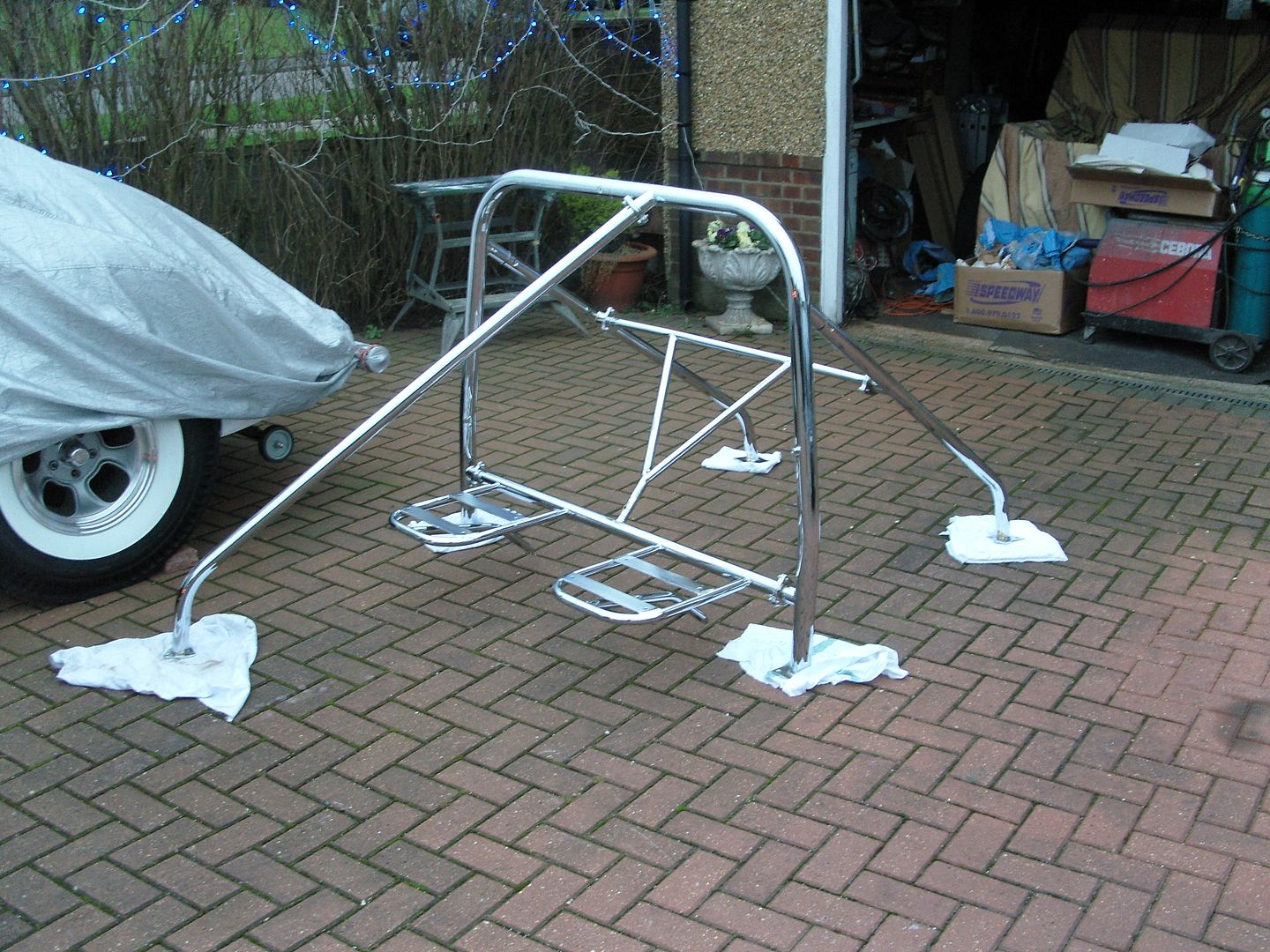
Got a call from the chrome plater today to come and collect my xmas pressie
He had plated all my front springs, a few small parts and finished off my rollcage, If its not raining tomorrow i will put the cage together for a pic.
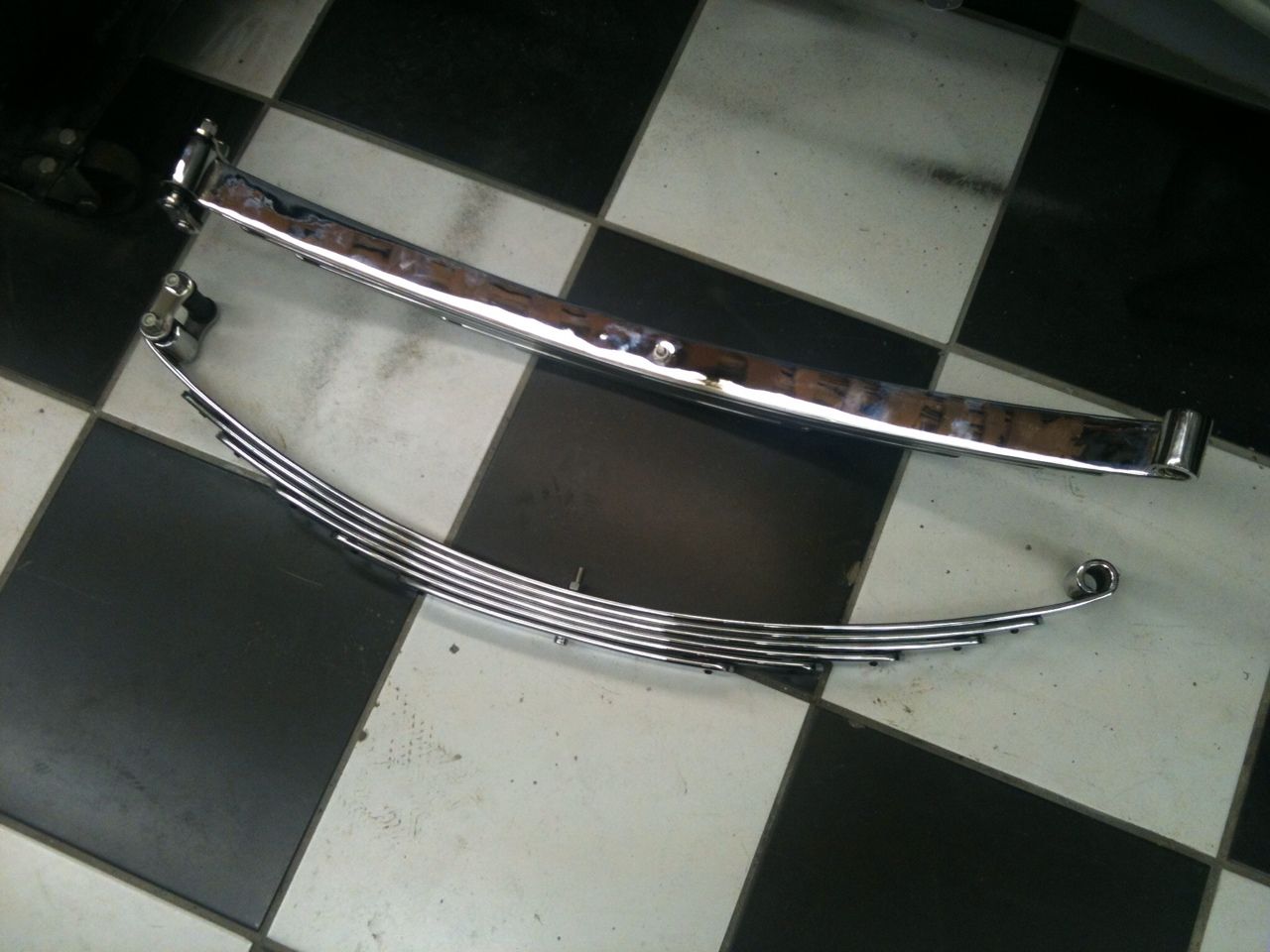
Happy xmas to you all
Firstly i bored out the shape and then turned the outside shape into the bar, then the outside was sanded to a nice radius.
The first one came out perfect
But i screwed up on the second one by taking off to much material, these are only 1/16" thick so it was easily done :eek:
I always say everybody screws up occassionaly but the important thing is how you rescue the situation and save the day by not having to remake another !!!
Welding was my first thought, Now i don't do much aluminium welding and certainly not on something this thin !!! Anyway popped over to see my mate Gary and we decided to have a go at it, as soon as the TIG sparked up it blew a hole so it was decided to run 2 beads 1/4" apart with 1.6mm rod and then fill in the gap between with 3mm rod, It worked a treat although doesn't look pretty !!!
Back at the workshop it went back in the lathe and the inside was rebored and cleaned out, then the outside was recontoured and sanded. A liner was made to be a slide fit inside so it could be gripped securley in the chuck.
A quick wipe up on the polisher and the job was done, 3 equidistant holes were drilled for machne screws that secure it to the wheel hub.
Had to paint some kitchen cabinet doors today
so thought while i had the gun out i would do a test piece to see what my Blue flake was going to look like.I chose the master cylinder as I had already smoothed it out a bit.
First up i gave it a couple of coats of Epoxy primer
After it had dried it got a quick key up with 600 wet and a coat of Black epoxy on it, I've decided to use a Black basecoat this time as it will save me a lot of work when i paint the body, I can primer it in Black and then go straight on with the blue flake therefore saving money on bascoat and time.
Got a call from the chrome plater today to come and collect my xmas pressie
He had plated all my front springs, a few small parts and finished off my rollcage, If its not raining tomorrow i will put the cage together for a pic.
Happy xmas to you all
langy
langys rodshop
- Messages
- 6,095
- Location
- London
Nice to get back into the workshop today and work off all the festive food
Had to get my cage trial fitted together so it all went together easily as there is no room in the ar for fiddling around, had to sand the slip joints slightly and clear all the tapped holes out, There is a lot of copper, nickel & chrome on it for sure.
Here's one of the wheels fitted, ignore the fact i put the springs back on the wrong way round , the pins are off set and i didnt notice till it was back on the ground.
Fitting the spindle mounts did exactly what i wanted by moving the wheel inboard a few inches, the old wheels were pushed out by the adaptor in the disc kit and the answer would of been to narrow the axle slightly.
Today i took the wheel to an expert, he was a really nice bloke and even let me have a go on a scrap magnesium rim, Its very much like welding ally, except the gas mix is 50/50 argon/helium and the rod is obviously different, we used a az101 filler rod. The arc is also much shorter than aluminium and everything has to be very very clean. Also he preheated it.
I learn't a lot of this old guy today and now would'nt hesitate to have a go myself.
Unfortunately he didn't finish the job as he ran out of rods
.
Well not much progress to speak of but today i'm a very happy chappy, Got a call from the wheel repairer to say my Spindle mount mag welding was done, They did an absolutely outstanding job and you would think it had never been damaged !!! They also sent it for crack testing and gave me a certificate to prove its ok.
They couldn't remachine it as their lathe was down but luckily i knew someone that had a big faceplate on a lathe, 24 hrs later it was done (thanks Brian)
Before
After
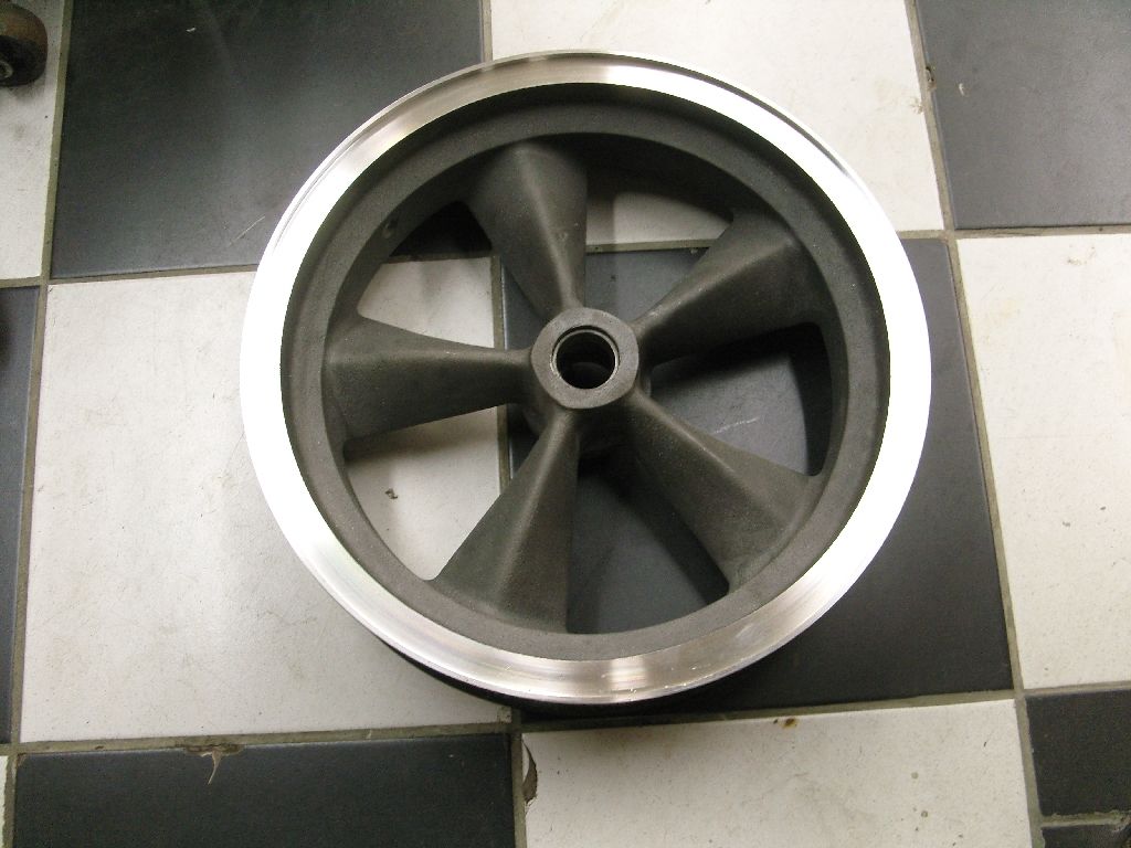
langy
langys rodshop
- Messages
- 6,095
- Location
- London
I had a slice of good fortune last week I had ordered a 8/71 blower kit from the states but this has taken longer than expected
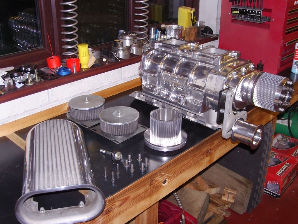
Meanwhile i was offered a complete Weiand 8/71 small block chevy kit for considarably less so i just altered my order to not have the blower.
Anyway i took the plunge and got it, I have to make a longer snout but its only a bit of work so don't mind considering i saved over $1500
More good news today when i got an email saying my intake was on its way to my shippers and would be here next thursday
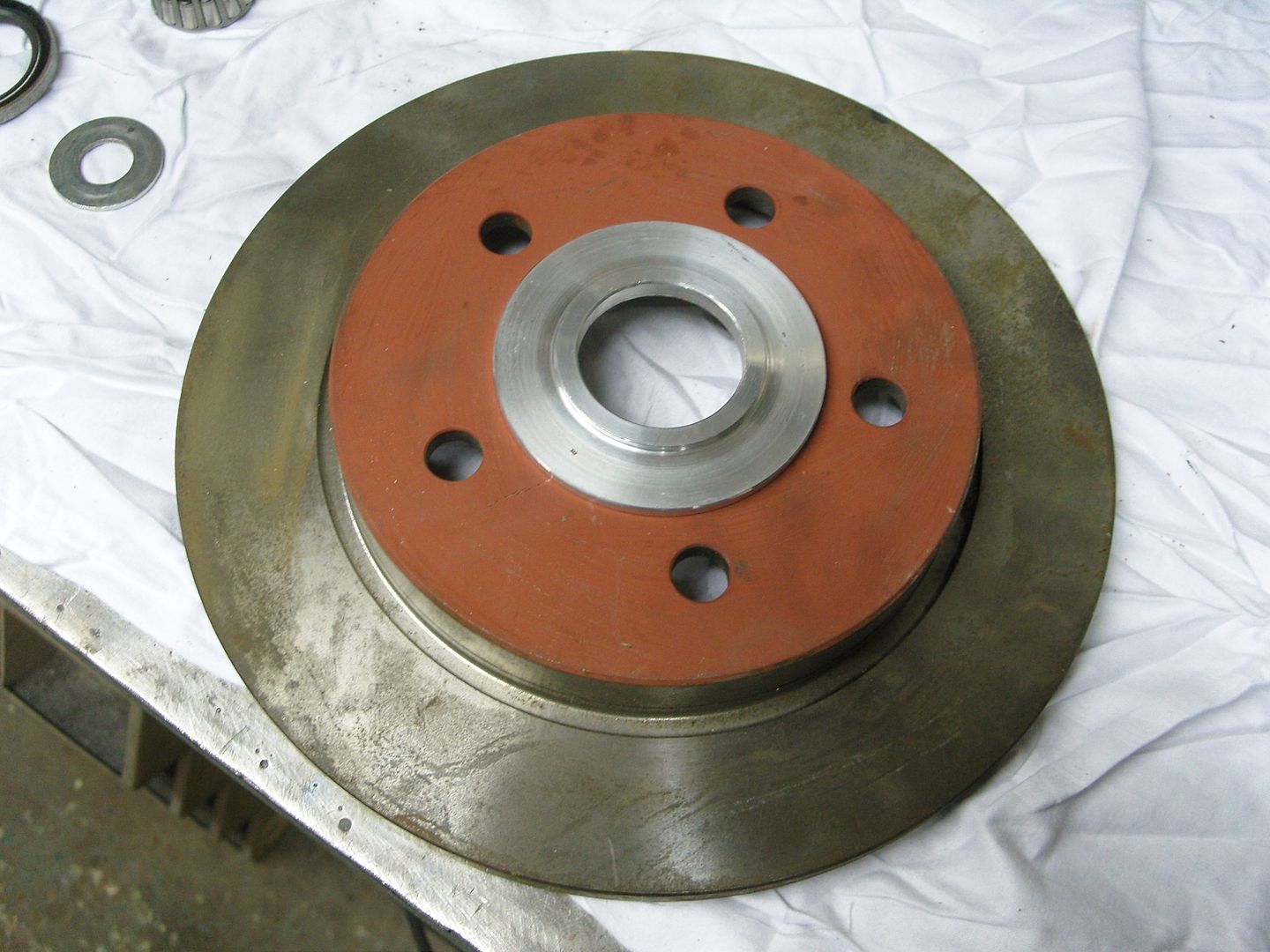
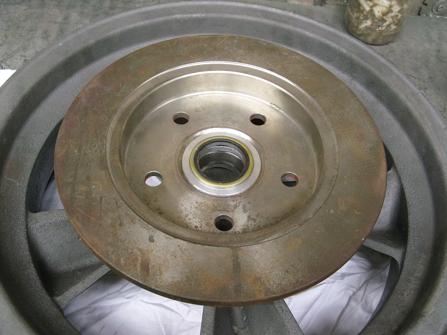
Sitting here with food poisioning , thanks mum !!! I got a call about how i fixed the discs on my spindle mount rims, didn't realise i had not posted it, so here ya go.
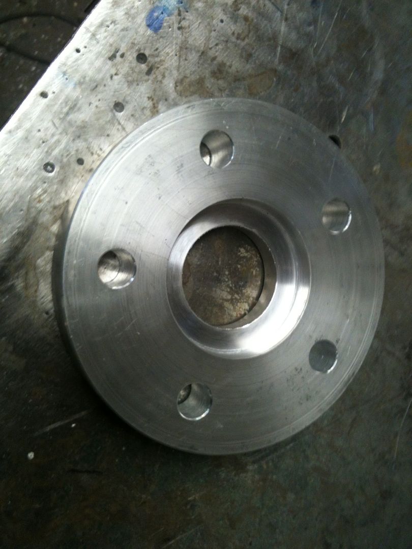
When i got the wheels an adaptor to centre up the disc to the wheel and mount the oil seal had already been made, I was told it all worked nicely but the more i looked at it the more i wasn't so sure of it, anyway i decided to re engineer it slightly, basically the same sort of thing but with a much larger OD so i could bolt the disc to the adaptor seperatly.
The original adaptor is on the right in the pic.
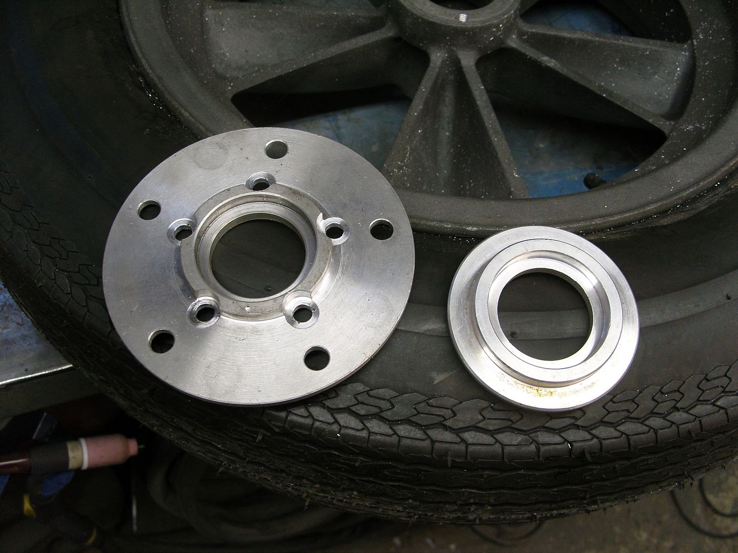
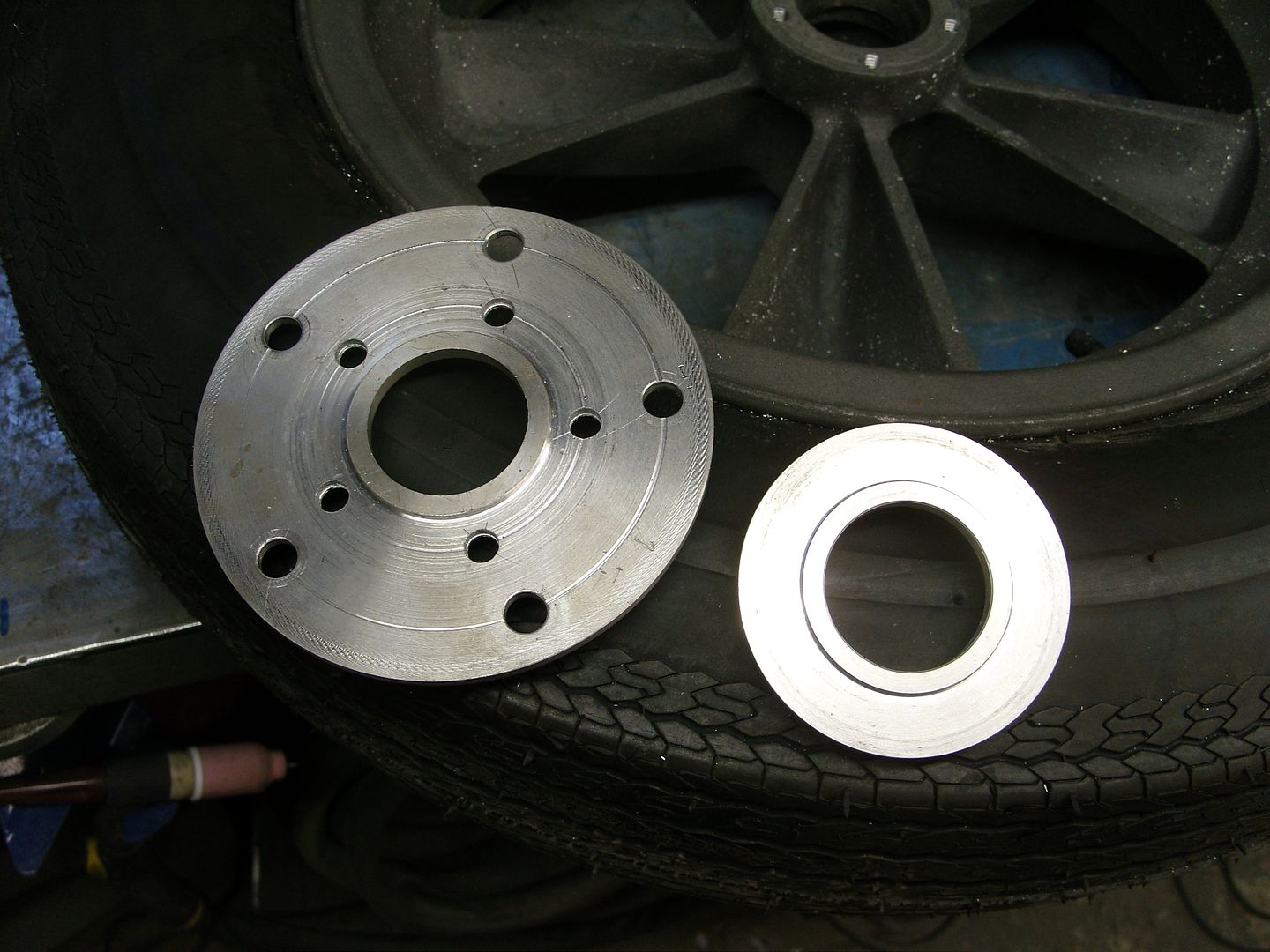
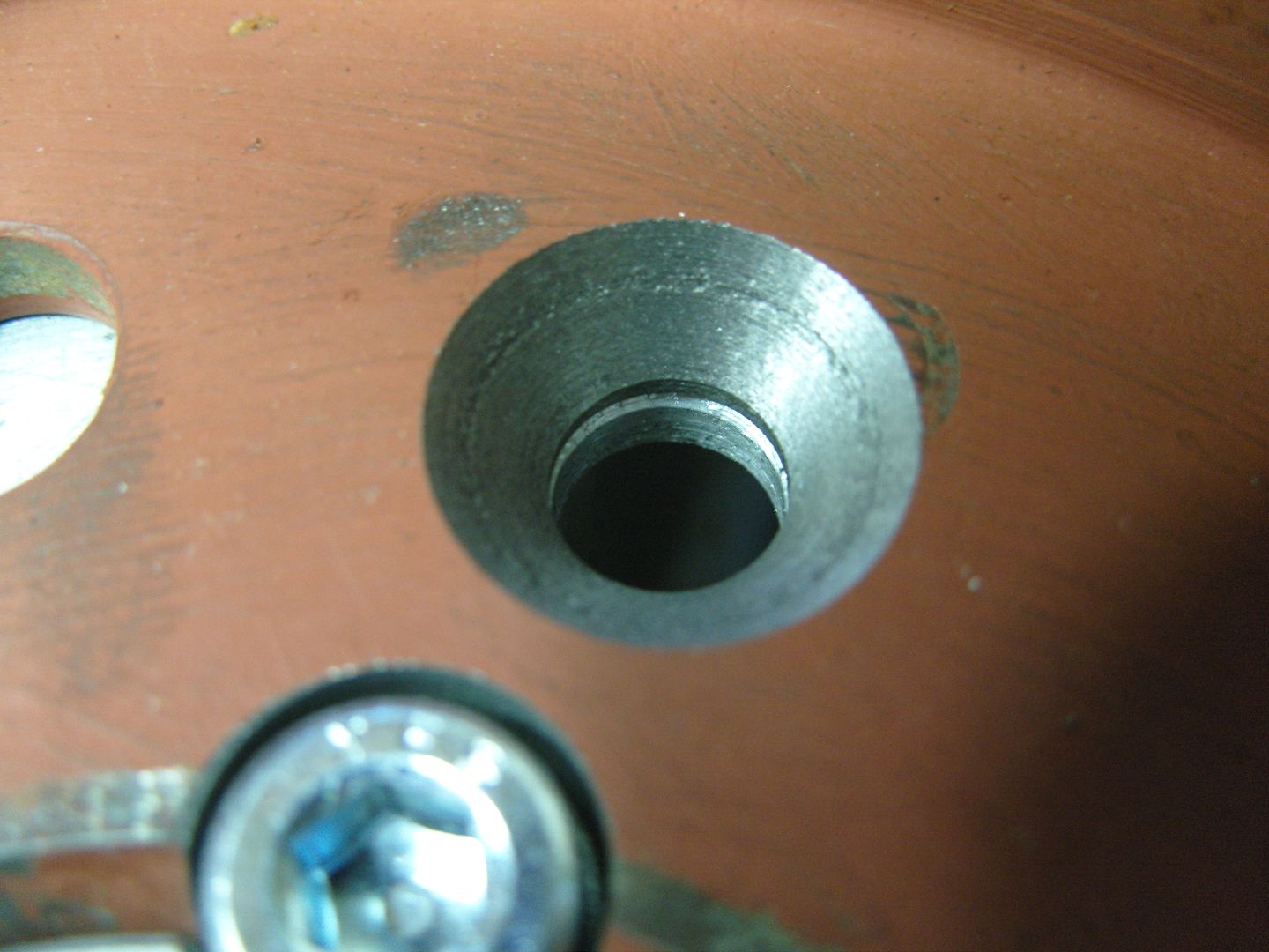
Next the adaptor was drilled with 5 x 5/16" holes on a 2.75" pitch circle and located on the wheel hub and the holes spotted on the drill press. the holes were then counter bored to accept allen bolts, the outer holes that bolt the disc on were drilled 3/8" to accept 3/8" hi tensile bolts.
The holes in the wheels were then drilled and tapped 5/16" UNC
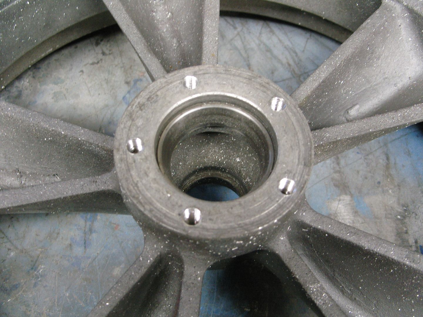
Next the discs were milled out to clear the bolt heads & the outer holes drlled.
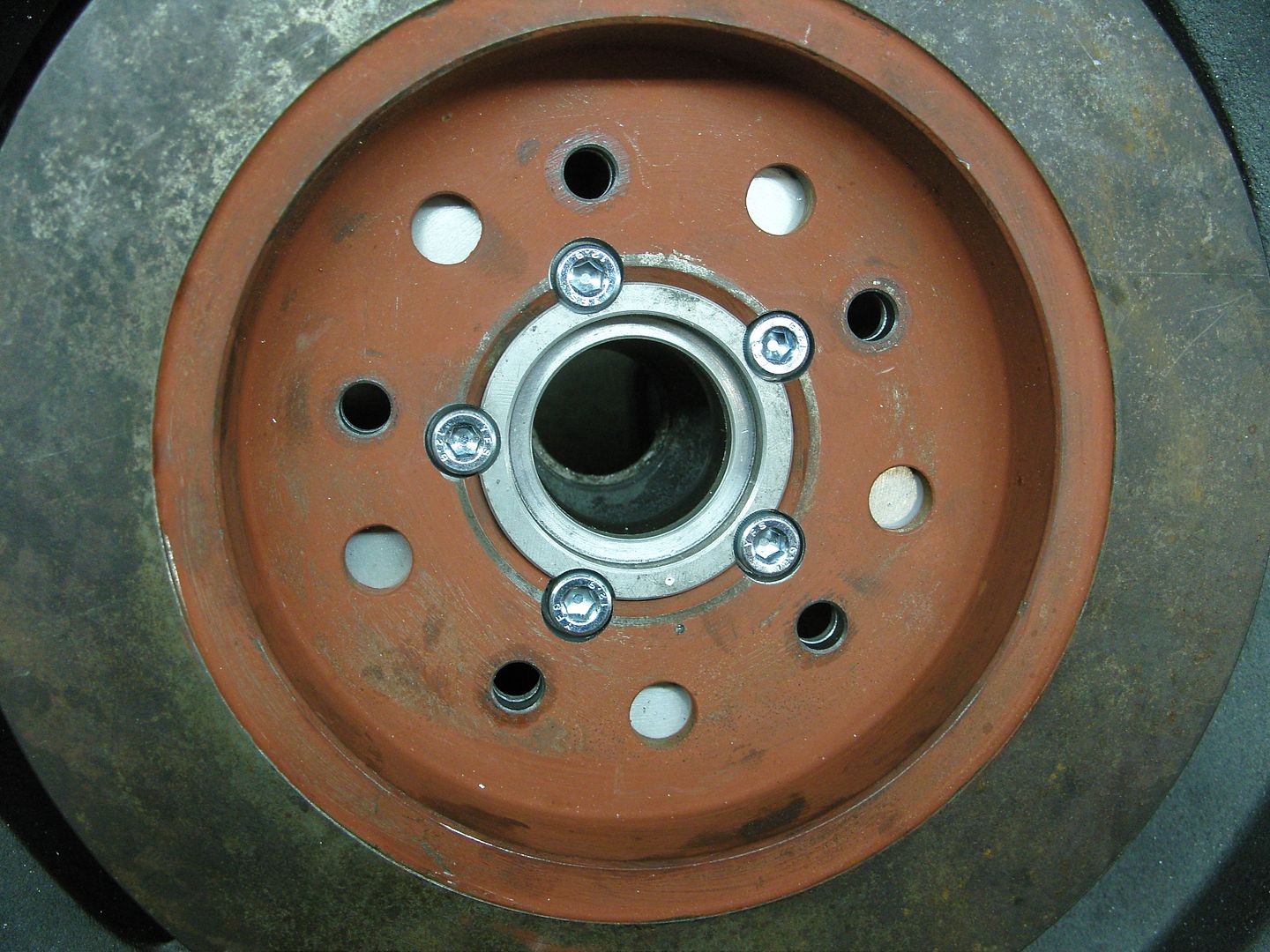
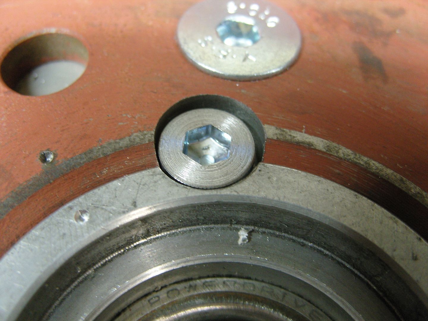
Centre punch marks were made to align everything.
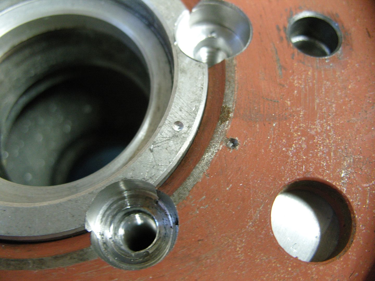
There was a slight clearence problem with the disc bolts so we fitted counter sunk socket cap screws and the holes counter sunk accordingly.
The nuts for the disc bolts could not be Nyloks because there was heat involved so we used Aero locking nuts which are mechanical locking.
Heres the disc fitted. the disc hub and adaptor wil get painted satin black.
 for looking
I had ordered a 8/71 blower kit from the states but this has taken longer than expected Meanwhile i was offered a complete Weiand 8/71 small block chevy kit for considarably less so i just altered my order to not have the blower.
Anyway i took the plunge and got it, I have to make a longer snout but its only a bit of work so don't mind considering i saved over $1500
More good news today when i got an email saying my intake was on its way to my shippers and would be here next thursday
Sitting here with food poisioning , thanks mum !!! I got a call about how i fixed the discs on my spindle mount rims, didn't realise i had not posted it, so here ya go.
When i got the wheels an adaptor to centre up the disc to the wheel and mount the oil seal had already been made, I was told it all worked nicely but the more i looked at it the more i wasn't so sure of it, anyway i decided to re engineer it slightly, basically the same sort of thing but with a much larger OD so i could bolt the disc to the adaptor seperatly.
The original adaptor is on the right in the pic.
Next the adaptor was drilled with 5 x 5/16" holes on a 2.75" pitch circle and located on the wheel hub and the holes spotted on the drill press. the holes were then counter bored to accept allen bolts, the outer holes that bolt the disc on were drilled 3/8" to accept 3/8" hi tensile bolts.
The holes in the wheels were then drilled and tapped 5/16" UNC
Next the discs were milled out to clear the bolt heads & the outer holes drlled.
Centre punch marks were made to align everything.
There was a slight clearence problem with the disc bolts so we fitted counter sunk socket cap screws and the holes counter sunk accordingly.
The nuts for the disc bolts could not be Nyloks because there was heat involved so we used Aero locking nuts which are mechanical locking.
Heres the disc fitted. the disc hub and adaptor wil get painted satin black.
langy
langys rodshop
- Messages
- 6,095
- Location
- London
Well we were blessed with sunny weather today so i thought i would get a few small jobs out of the way.
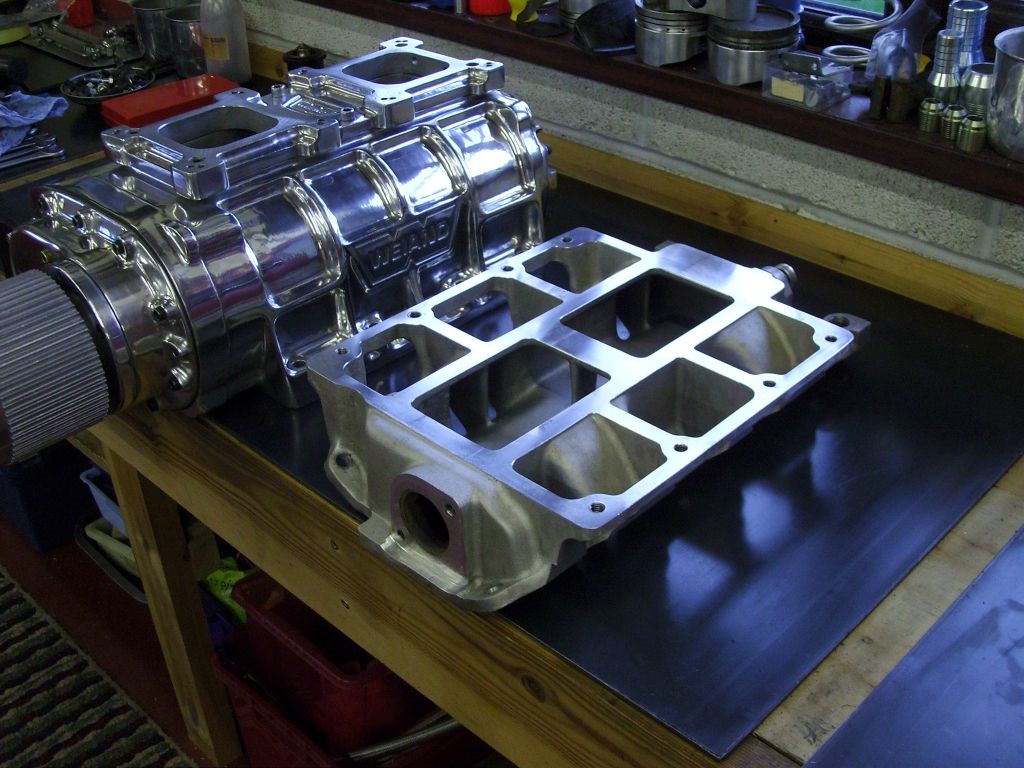
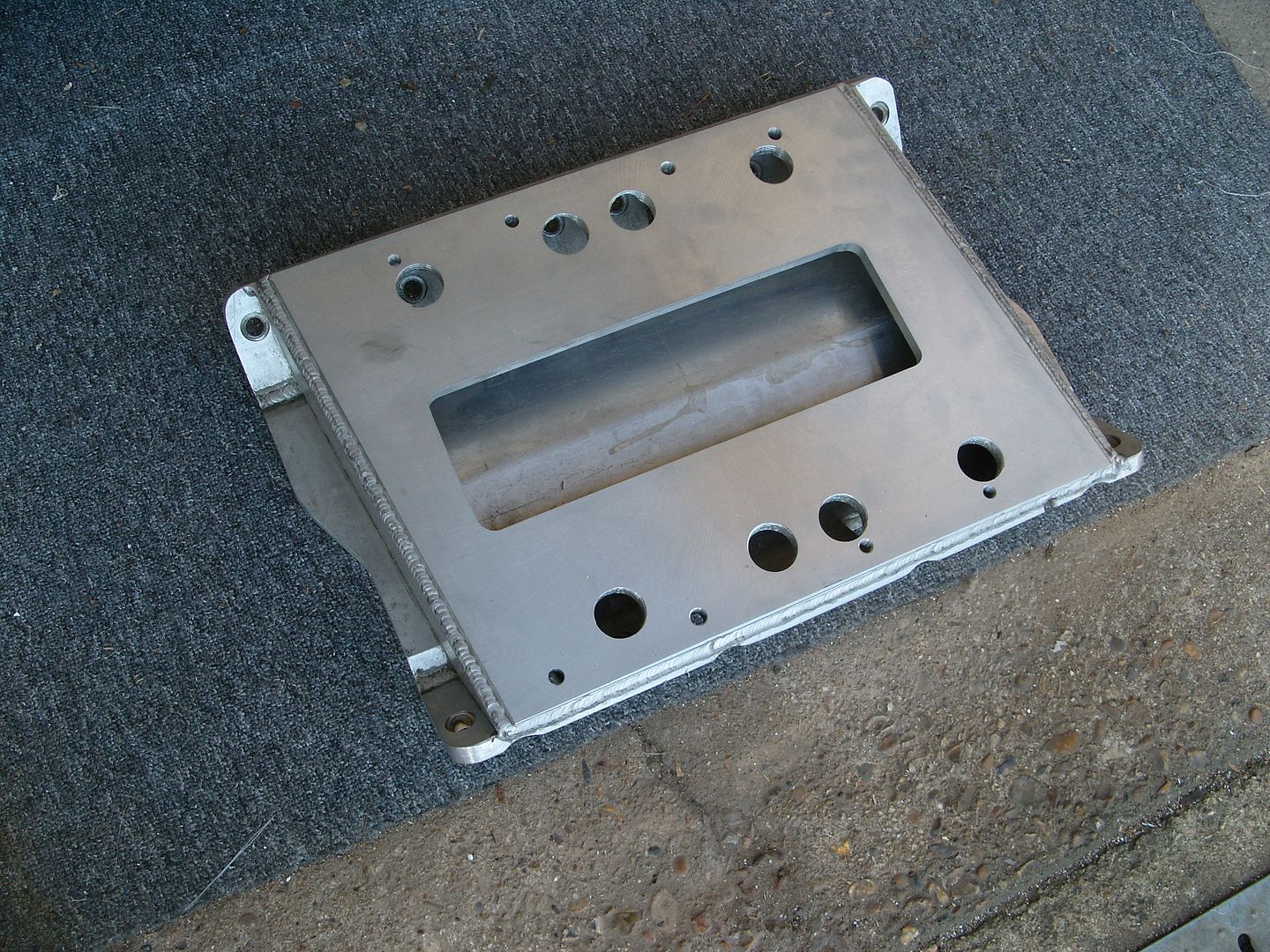
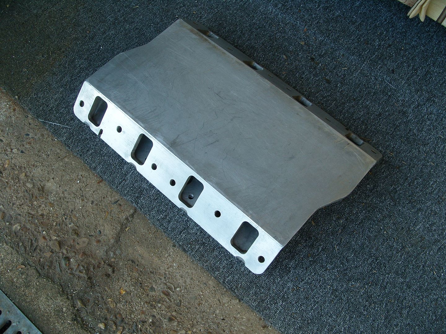
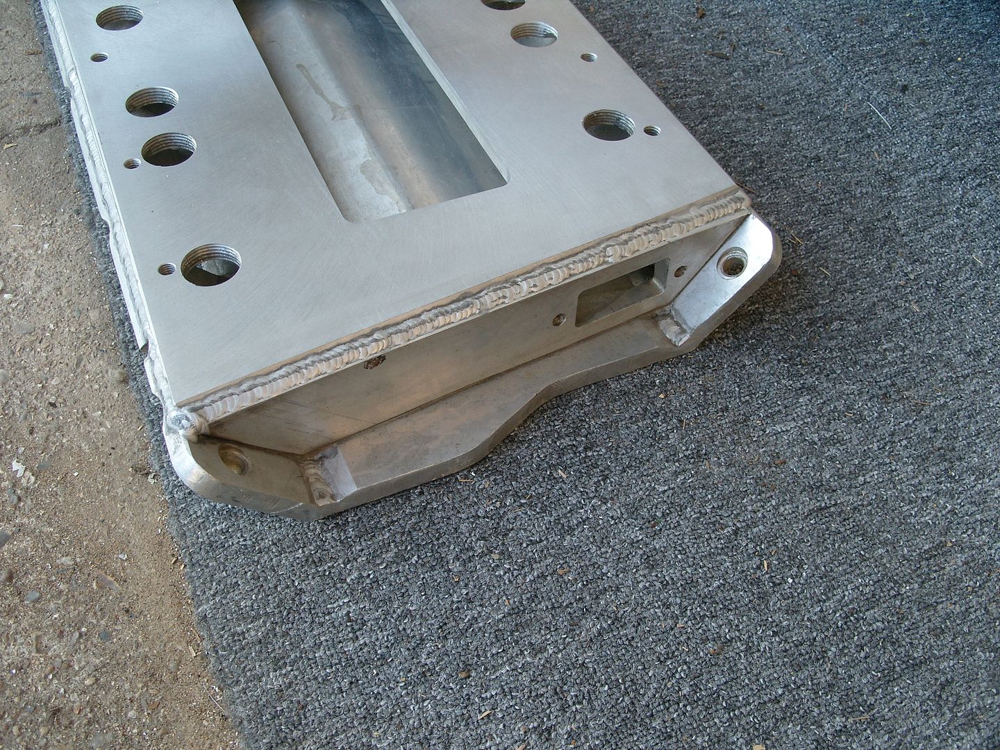
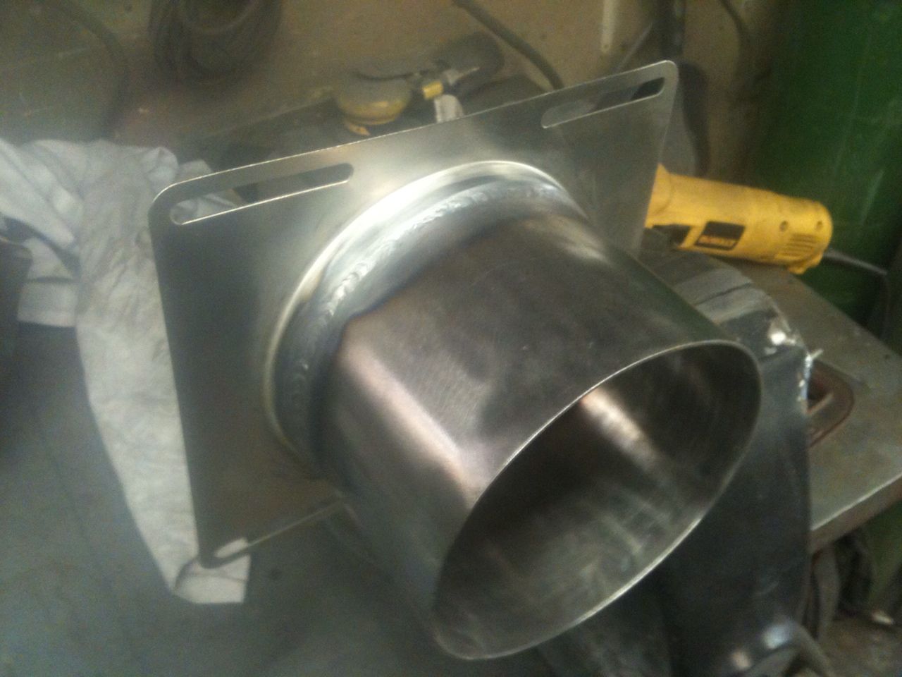
The blower i bought was for a SBC so an intake was fabricated from 1/2" aluminium plate.
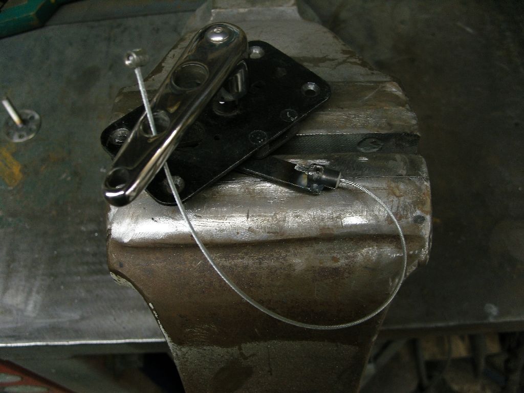
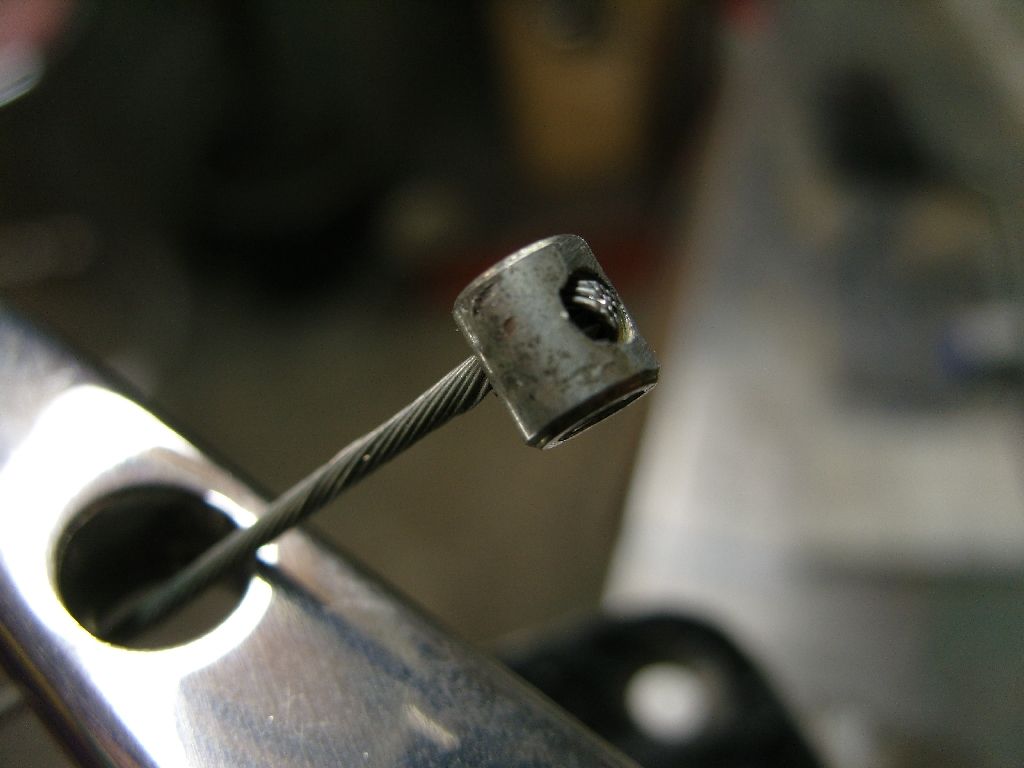
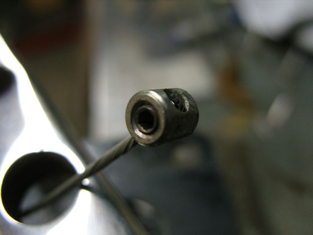
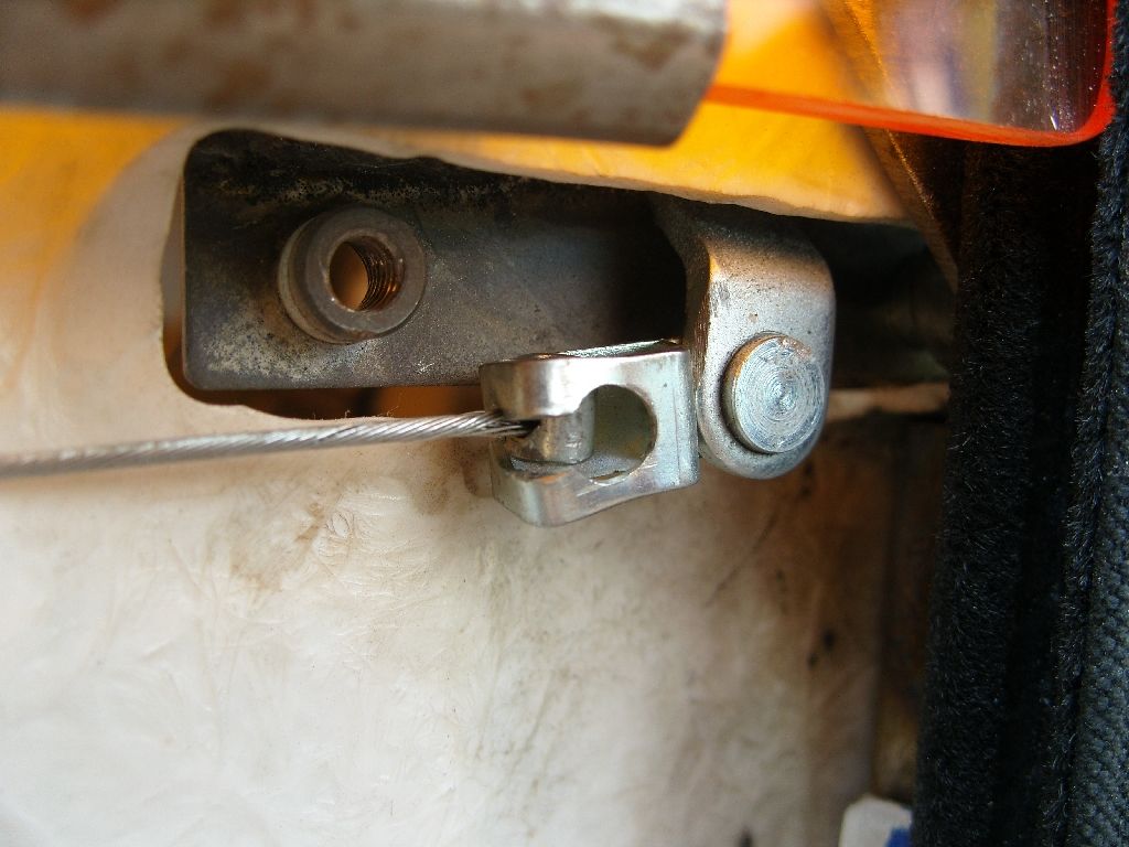
Another job to finish was the working mechanism for the outside door handle, winter set in before i had a chance to finish them.
They work by cables as it was the easiest way to miss the window when wound down. The cables are stainless bicycle cables. The handles are mounted on plates which fit inside the outer skin.

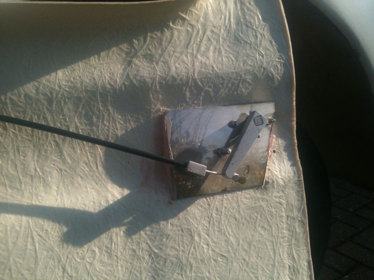
The spring is temporary until i find one the right length.
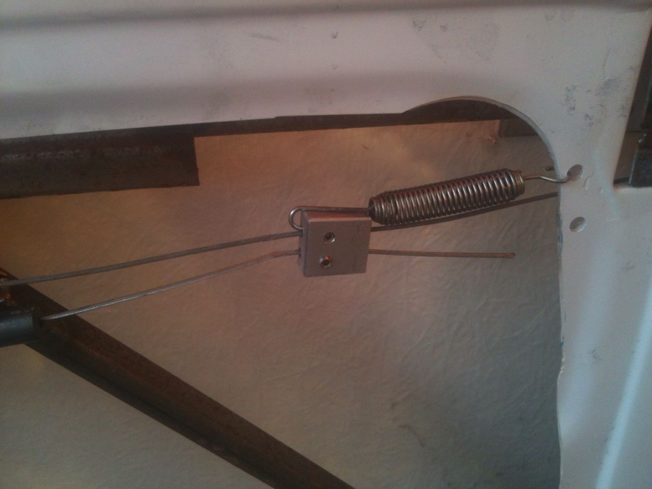
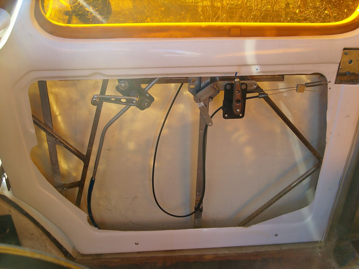
It all works really well
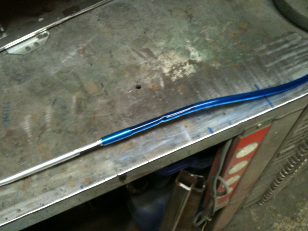
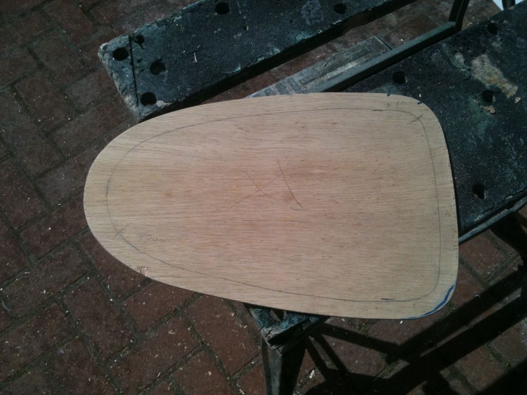
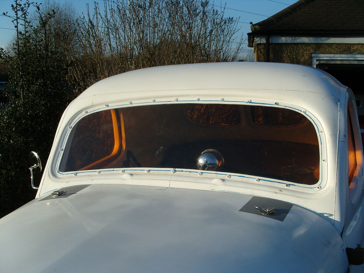
I also fitted the windscreen, this is 1/4" Lexan mainly to keep the weight down. A template was made and the fixing holes drilled, then this was transferred to the Lexan sheet.
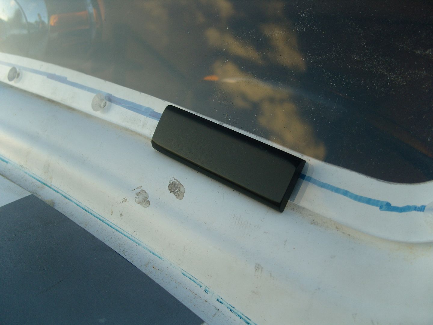
I found a 1" wide rubber which will be bonded on when painted.
Well the weather has been very kind the last few days and my old mate Garry Bennetts was staying over for the NSRA swapmeet on sunday, Garry has had a blower on every car he has owned and knows his blowers and suggested we should dummy mine up in the car to see how it all looked
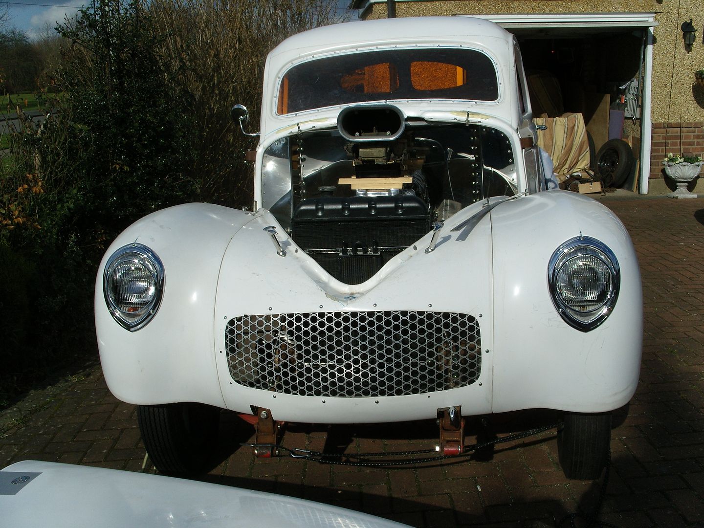
We got it all in position and was surprised it all fitted under the stock hood !!! This was due to me fitting the motor a little lower in the frame than usual. I really liked the sneaky pete look but over the next hour Garry convinced me it should stick up through the hood. then 7 of the boys north of the border turned up on the way to the Swapmeet and all said "its gotta stick out the hood" , It was settled
Heres a pic of it fitted under the stock hood line. The hood clears it by about 3/8"
Here its spaced up with 1" Phenolic spacers and bits of wood under the carbs, still not enough to stick out of the hood but i don't want to go with thicker spacers so I decided i would make up some spacers for the scoop and raise it slightly, I'm looking to have the scoop intake just clear of the hood lip.
Heres a pic of it raised slightly, better ???
Ideally i would like a thicker carb mounting plate as the existing one is only 1/2" thick, something around 3" thick would be perfect, packed up at this point has it would have to be ordered from the states
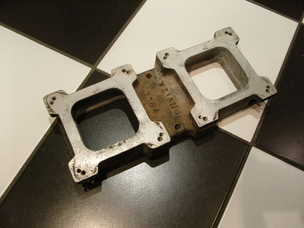
This morning we set off for the NSRA swapmeet and after about 15 mins of being there i spied Nigel from UK Blowers walking towards me, got chatting and suddenly realised in his left hand was a 2.5" dual carb mounting plate, near enough to do the job, I couldn't believe it !!!
Its even a Weiand plate the same as my blower Anyway I asked about it and Nigel just said have it, Thanks Nigel your a star !!!
Next job was to rough cut the hole in the hood, no going back now !!! Unfortunately in my excitement i forgot to take a picture, Will take one tomorrow when i mock it up again.
Thanks for looking.
The blower i bought was for a SBC so an intake was fabricated from 1/2" aluminium plate.
Another job to finish was the working mechanism for the outside door handle, winter set in before i had a chance to finish them.
They work by cables as it was the easiest way to miss the window when wound down. The cables are stainless bicycle cables. The handles are mounted on plates which fit inside the outer skin.
The spring is temporary until i find one the right length.
It all works really well
I also fitted the windscreen, this is 1/4" Lexan mainly to keep the weight down. A template was made and the fixing holes drilled, then this was transferred to the Lexan sheet.
I found a 1" wide rubber which will be bonded on when painted.
Well the weather has been very kind the last few days and my old mate Garry Bennetts was staying over for the NSRA swapmeet on sunday, Garry has had a blower on every car he has owned and knows his blowers and suggested we should dummy mine up in the car to see how it all looked
We got it all in position and was surprised it all fitted under the stock hood !!! This was due to me fitting the motor a little lower in the frame than usual. I really liked the sneaky pete look but over the next hour Garry convinced me it should stick up through the hood. then 7 of the boys north of the border turned up on the way to the Swapmeet and all said "its gotta stick out the hood" , It was settled
Heres a pic of it fitted under the stock hood line. The hood clears it by about 3/8"
Here its spaced up with 1" Phenolic spacers and bits of wood under the carbs, still not enough to stick out of the hood but i don't want to go with thicker spacers so I decided i would make up some spacers for the scoop and raise it slightly, I'm looking to have the scoop intake just clear of the hood lip.
Heres a pic of it raised slightly, better ???
Ideally i would like a thicker carb mounting plate as the existing one is only 1/2" thick, something around 3" thick would be perfect, packed up at this point has it would have to be ordered from the states
This morning we set off for the NSRA swapmeet and after about 15 mins of being there i spied Nigel from UK Blowers walking towards me, got chatting and suddenly realised in his left hand was a 2.5" dual carb mounting plate, near enough to do the job, I couldn't believe it !!!
Its even a Weiand plate the same as my blower
Anyway I asked about it and Nigel just said have it, Thanks Nigel your a star !!!
Next job was to rough cut the hole in the hood, no going back now !!! Unfortunately in my excitement i forgot to take a picture, Will take one tomorrow when i mock it up again.
Thanks for looking.
langy
langys rodshop
- Messages
- 6,095
- Location
- London
Well the thicker carb mounting pate has helped but still couldn't get the scoop where i wanted it, don't want it sticking right out really as i can't see much out of the screen as it is !!! The scoop has been up & down like a hookers knickers
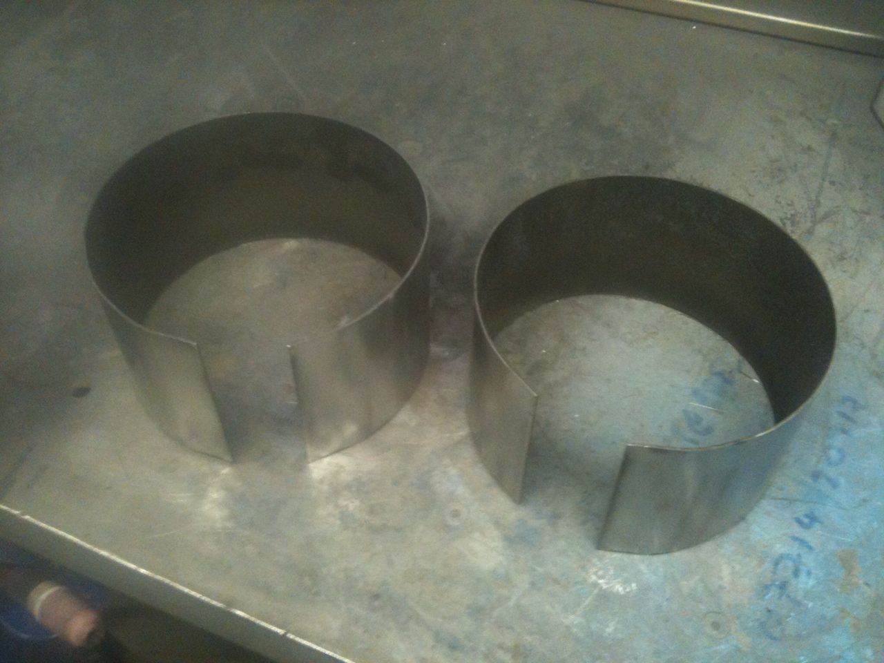
I decided to lift the plates that attach the scoop to the carbs, A couple of pieces of flat were rolled up and welded to the plates, this gives me a 3" lift, I've ordered a pair of 2" thick carb spacers so i will trim 1" of these later.
It now sits just how i wanted it, not sticking up too much, just enough to know its there.
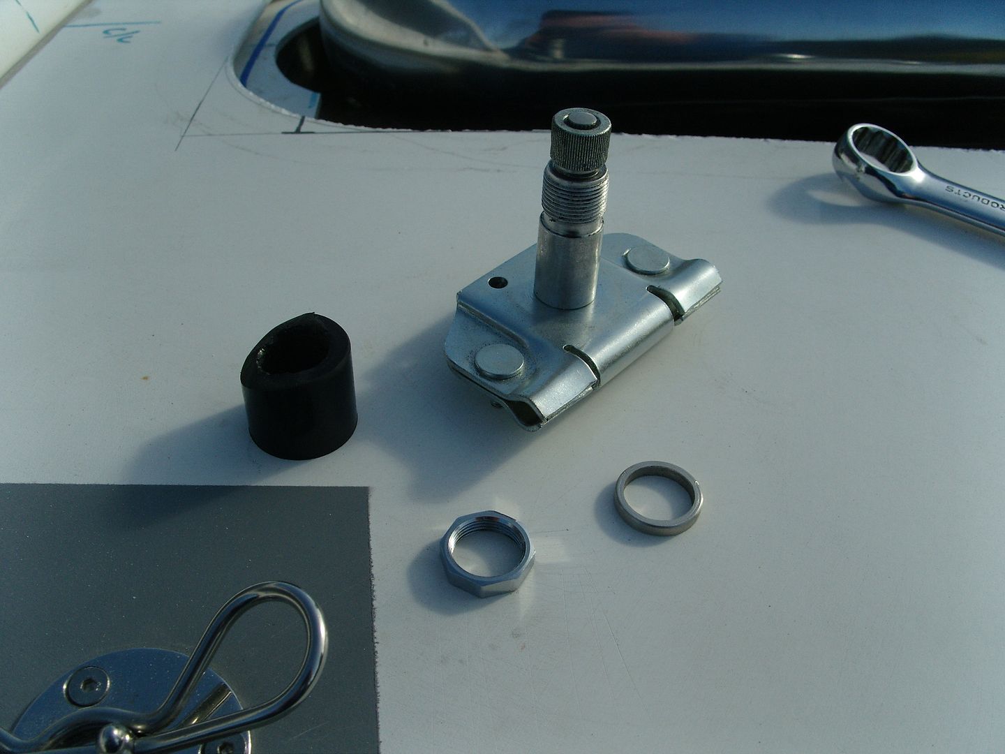
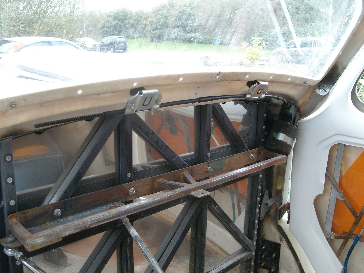
Managed to sort another job last night in a couple of hours :yes:
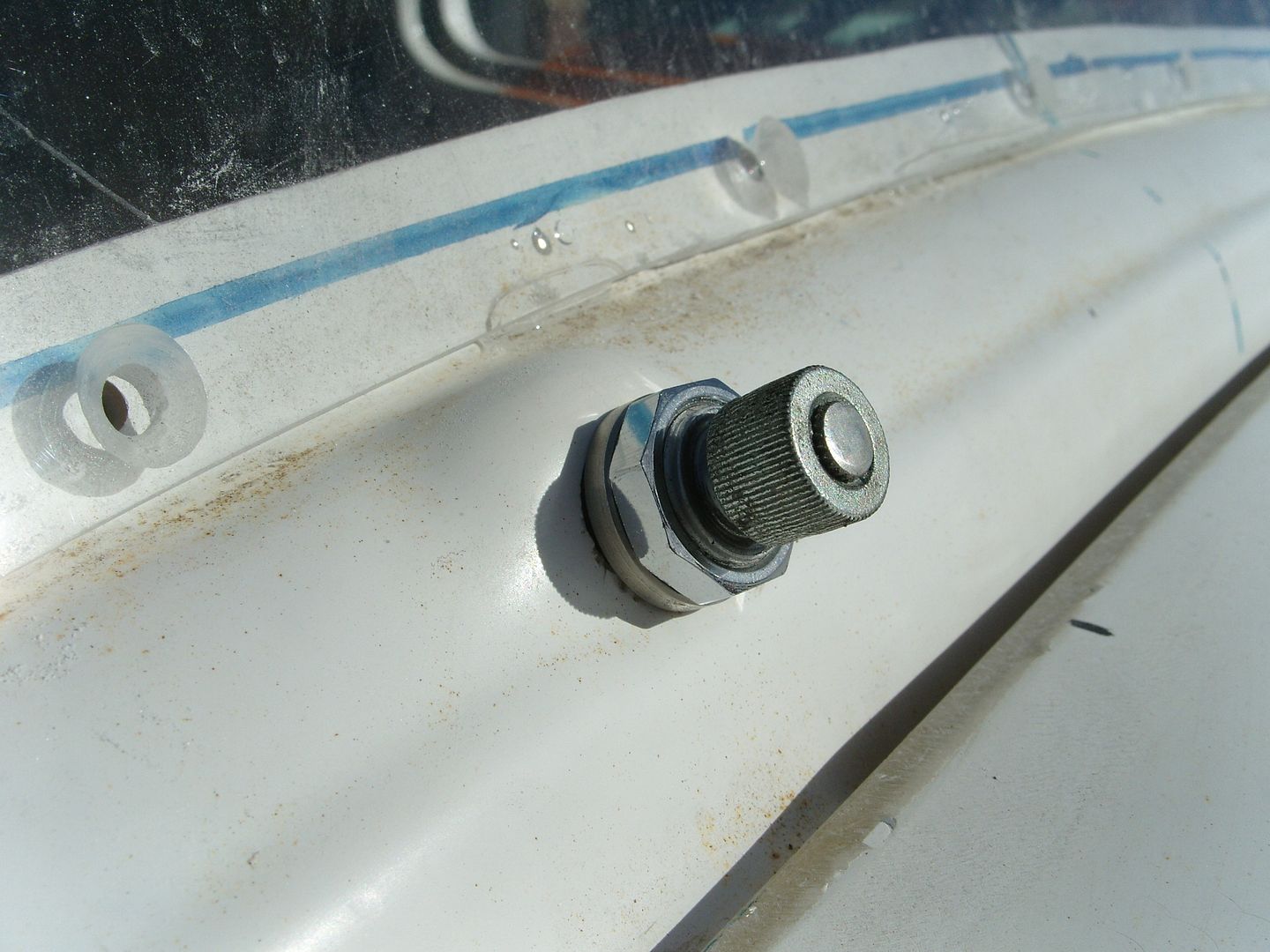
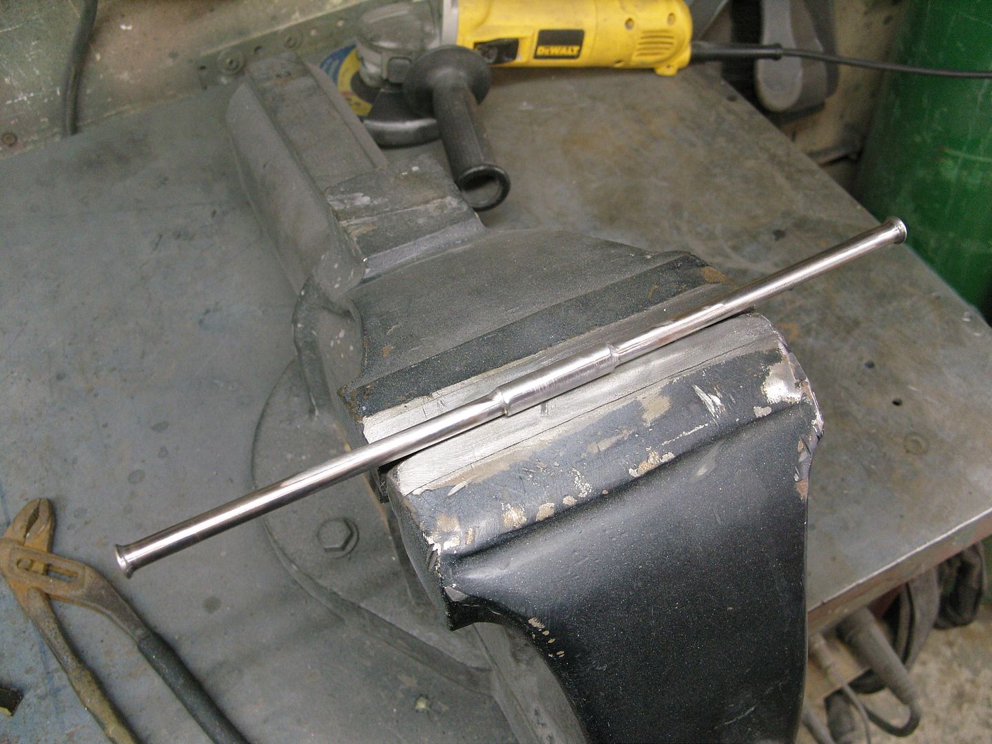
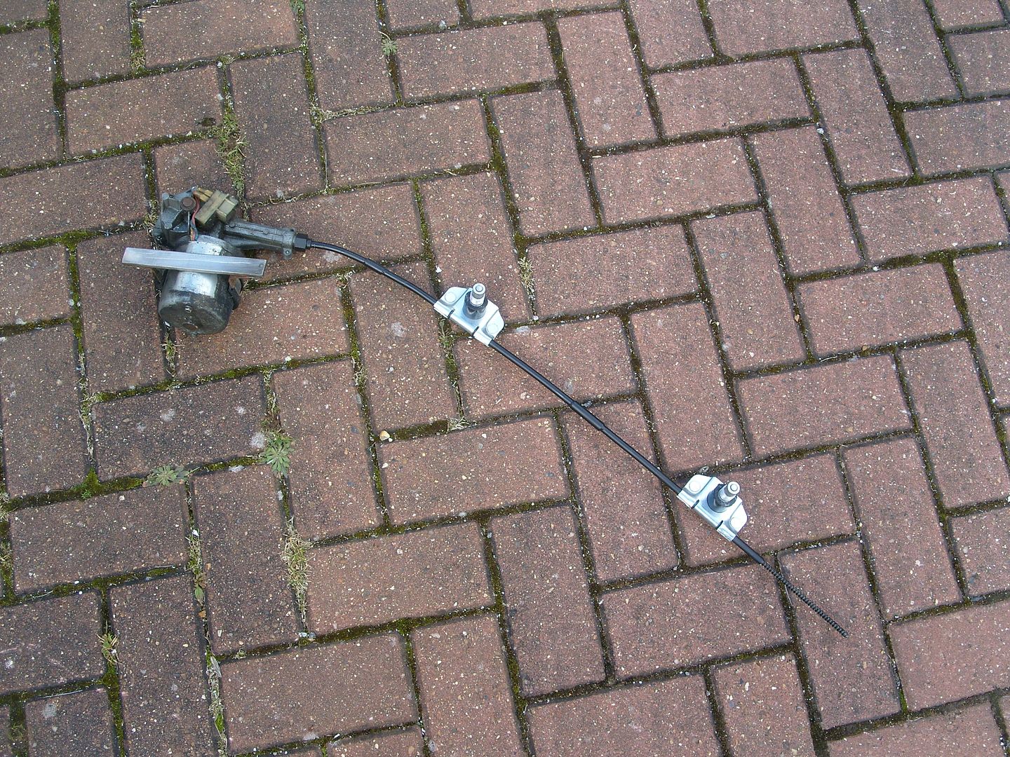
Picked up a mini wiper system at the swapmeet and it's almost a perfect fit for the willys All it needed was 2 of the cable tubes shortening and went straight in ")
The wheel boxes needed a spacer with a slight angle on them to sit straight, these were made from some nylon bar, here's the parts and a wheel box fitted.
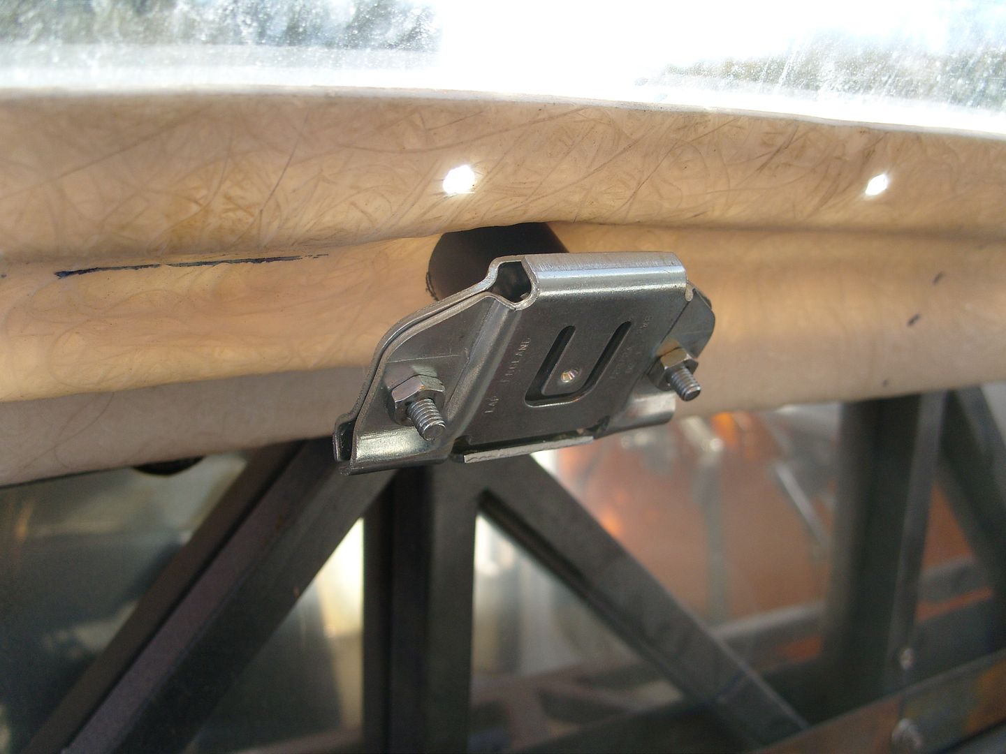
Next the tubes were shortened, didn't have anymore tube so joiners were turned on the lathe and soldered into the tube.
Completed assembly
Motor bolted into position
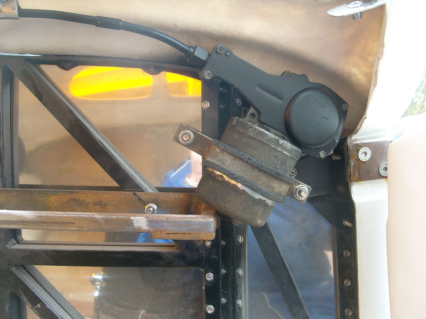
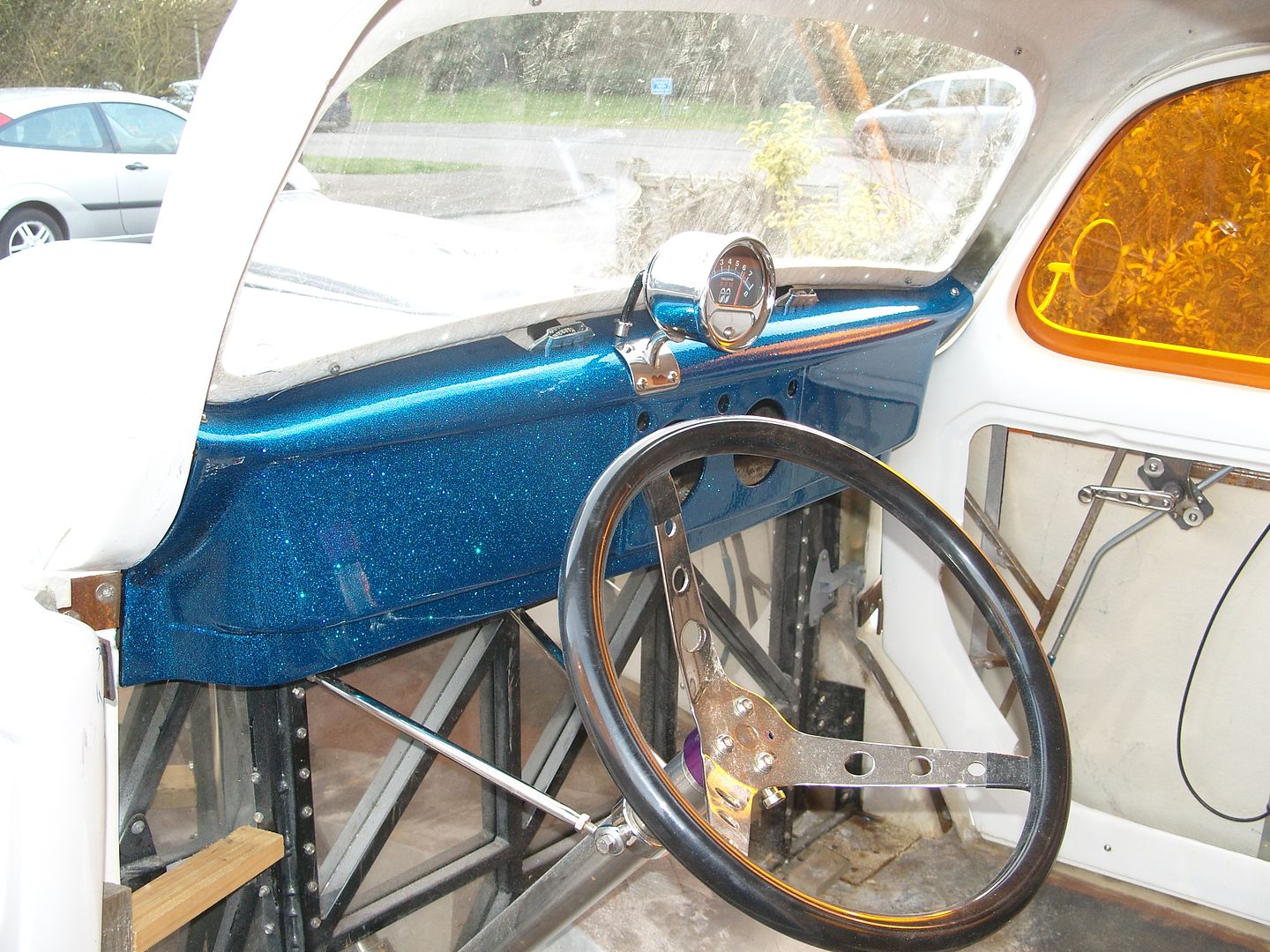
Dashboard refitted
:thanks:
I decided to lift the plates that attach the scoop to the carbs, A couple of pieces of flat were rolled up and welded to the plates, this gives me a 3" lift, I've ordered a pair of 2" thick carb spacers so i will trim 1" of these later.
It now sits just how i wanted it, not sticking up too much, just enough to know its there.
Managed to sort another job last night in a couple of hours :yes:
Picked up a mini wiper system at the swapmeet and it's almost a perfect fit for the willys
All it needed was 2 of the cable tubes shortening and went straight in The wheel boxes needed a spacer with a slight angle on them to sit straight, these were made from some nylon bar, here's the parts and a wheel box fitted.
Next the tubes were shortened, didn't have anymore tube so joiners were turned on the lathe and soldered into the tube.
Completed assembly
Motor bolted into position
Dashboard refitted
:thanks:
