


Making a Chassis Frame Alignment Jig
A full chassis jig is invaluable for assembling a chassis frame from scratch. This one is intended for major repairs to existing Renault 4 chassis and I've made a few compromises along the way to keep the jig simple and easy to make, and also made the occasional mistake. Here's the page I would like to have read before I started work.
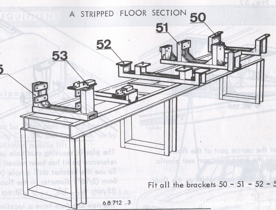
The jig is loosely based on a chassis checking jig from the factory workshop manual. It uses a C shaped channel which makes it handy to bolt attachments on.
Unfortunately C section channels have next to no torsional stiffness - the jig in the drawing would have been bolted to a steel floor for stiffness, but I've got other ideas for mine.
I think I can work around the lack of torsional stiffness from C section channel, but if I were to make the jig again I'd seriously consider using box section.
The steel for the jig consisted of 12m of 50mm*100mm C section channel with a thickness of 6mm for the center section and 9mm for top and bottom sections. This was cut to size by the steel supplier. I ordered 6m of 150mm*6mm plate for use in the brackets that would connect to the suspension mountings.
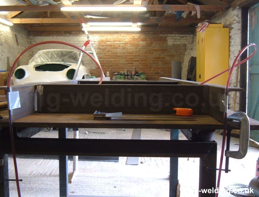
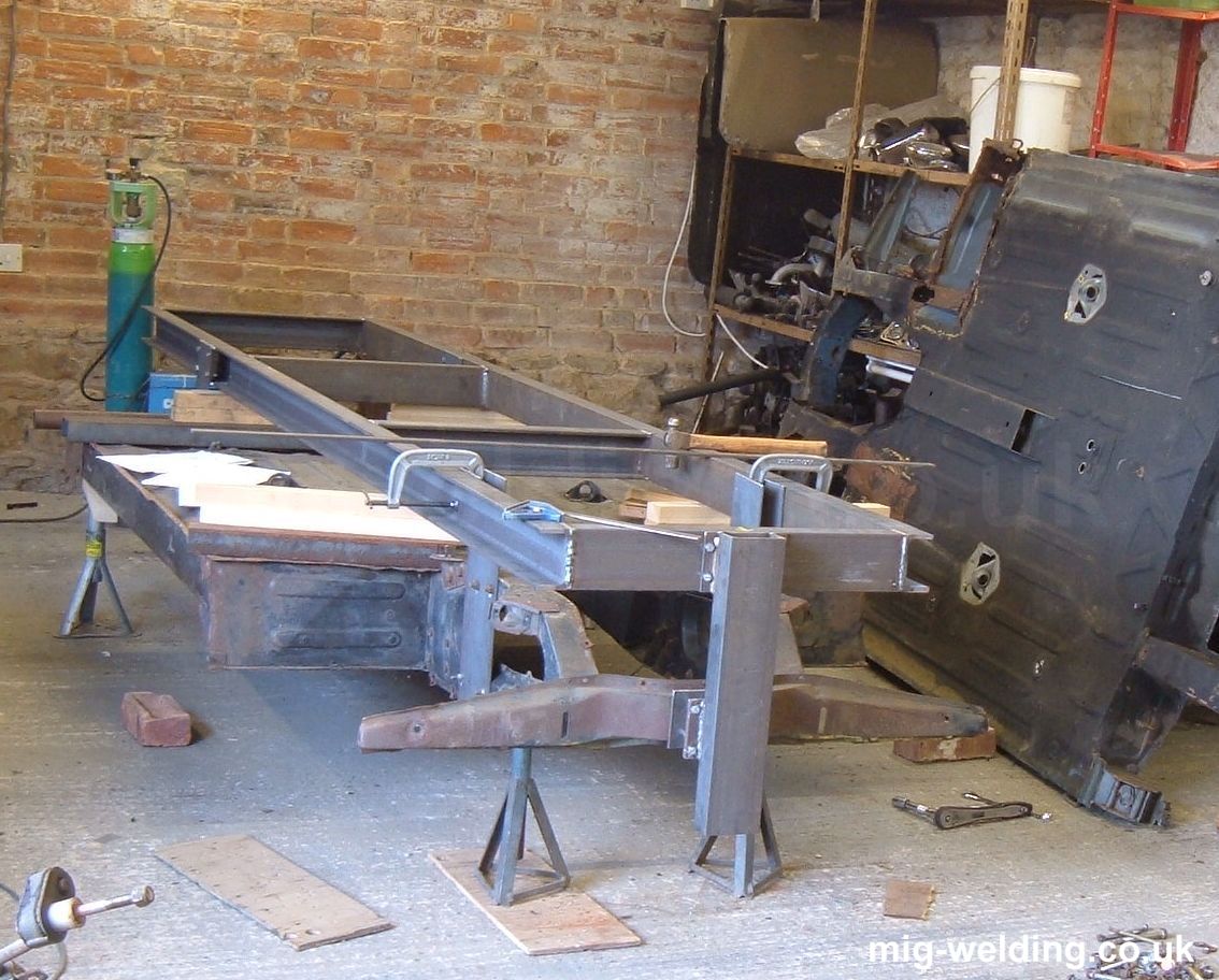
I'd been hoping to use my big steel workbench to position the jig, but found it was bent.

Prior to welding the jig was leveled by propping it with pieces of wood, then progressively thinner pieces of steel. The red wine level gauge came in very handy for checking the level.
It's a long length of clear plastic tube (intended for fish tanks) which has been filled with red wine. Gravity ensures that the level of wine at each end of the tube is at an identical height. Water doesn't work as accurately as it has too much surface tension and seems to stick inside the tube.
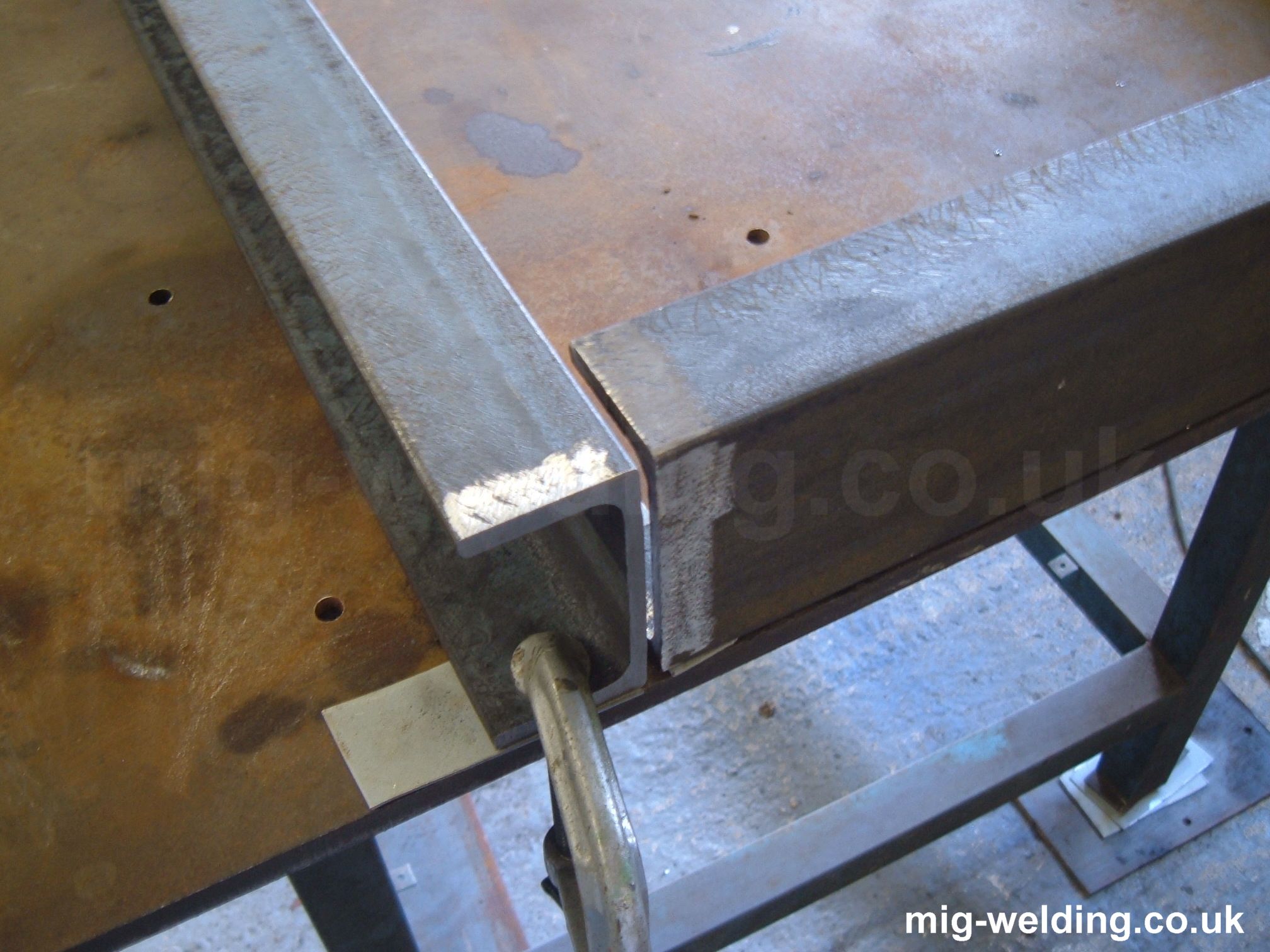
I'd designed the joints with a 5mm root gap between the parts I wanted to weld. That's quite a large root gap, but my 155 amp welder was going to need as much help as it could get - even on the maximum setting it's not up to the job of welding this thickness of steel.
I could have aided the welder further by cutting a V into the edges of the joint.
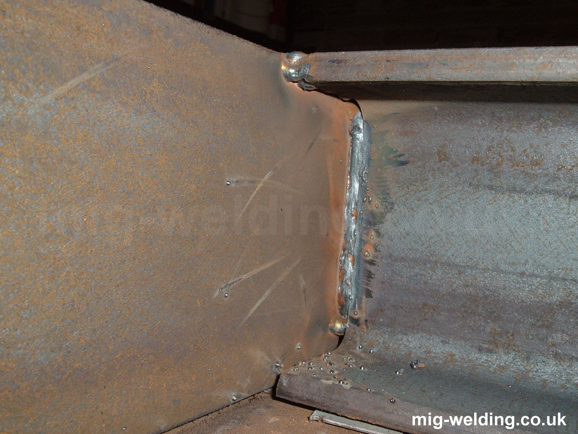
The welding was done using a pull technique on horizontal surfaces, and welding downwards on the vertical surface. I could have increased penetration by welding upwards, but my root gap was a little large and the weld was difficult to control when welding upwards.
The 155 amp welder isn't really up to this sort of work.
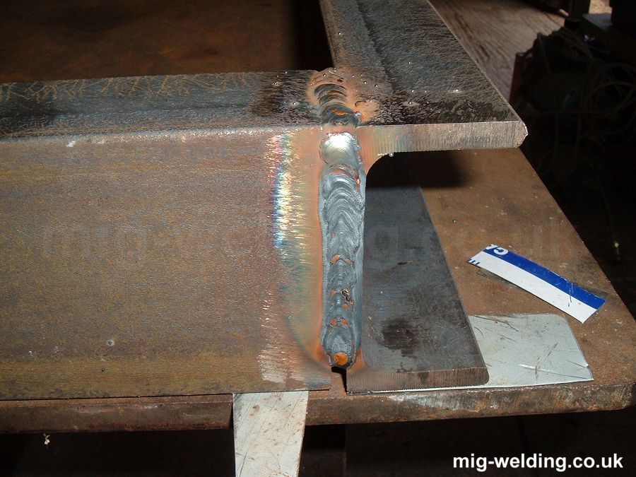
Penetration looks OK in the photograph but it's not as good as it looks. I've probably got reasonable weld strength only for about 50% through the joint.
My joint quality wouldn't be suitable for the framework in tall buildings, but it's perfectly strong and stiff enough for use in my chassis jig where high forces and fatigue aren't going to be an issue.
The manual provided a few helpful co-ordinates for suspension mounting position relative to the floor, but did not go into the detail required to build a jig. I used a known straight chassis to provide the missing dimensions.
All of the measurements were made relative to the front of the chassis jig and a straight edge positioned on top of the jig. The accuracy of measurements is quite surprising. Production tolerances for suspension mountings tend to be around 1.5mm, but I'm certain I'm within 0.5mm for all mounting points.
The chassis to the right will be the first to be welded using the jig. Rust has completely eaten away the connection between the front longitudinal members and sills, and the front of the chassis has bent as a result.
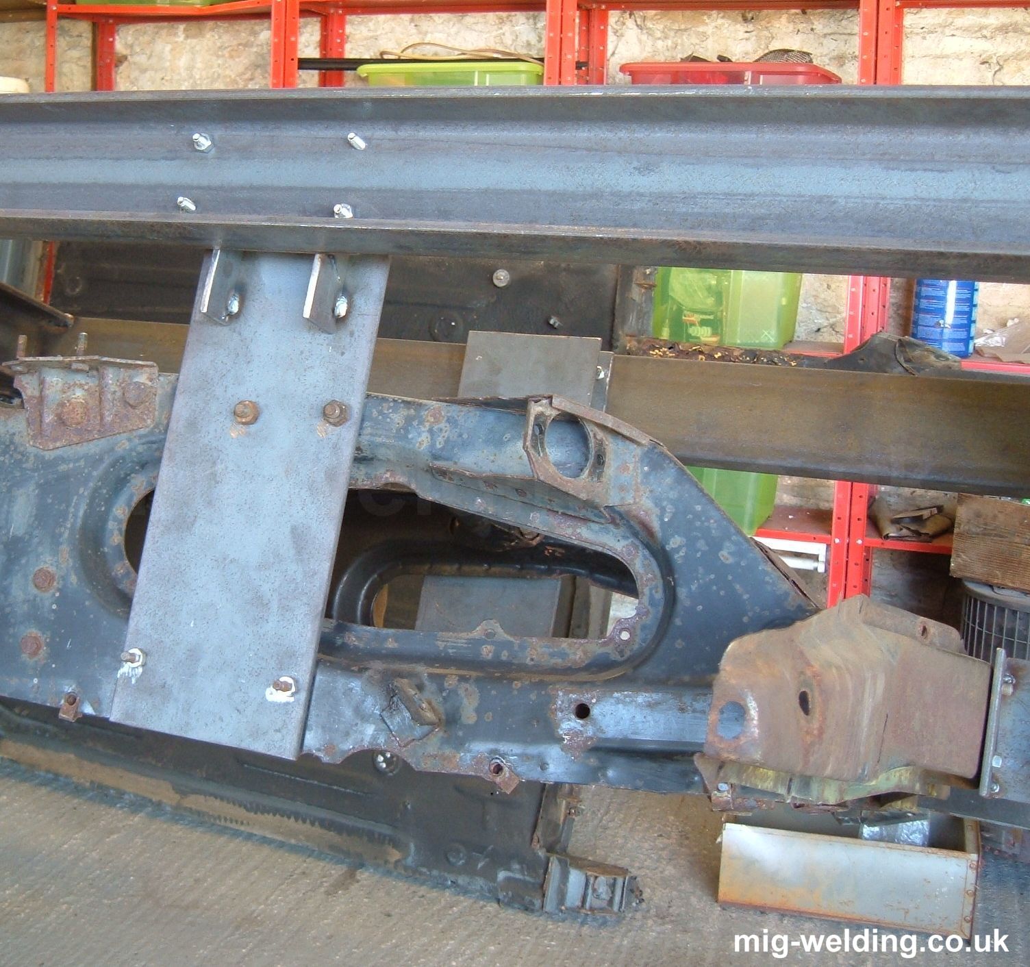
The jig was positioned about 125mm clear of the floor to allow access for a welding torch or angle grinder. The pick up points for the suspension mountings were cut from the 6mm steel sheet. The lateral stiffness is more than enough to allow a new piece of chassis to be positioned and tack welded in place, but there is flexibility to allow for differences between chassis.
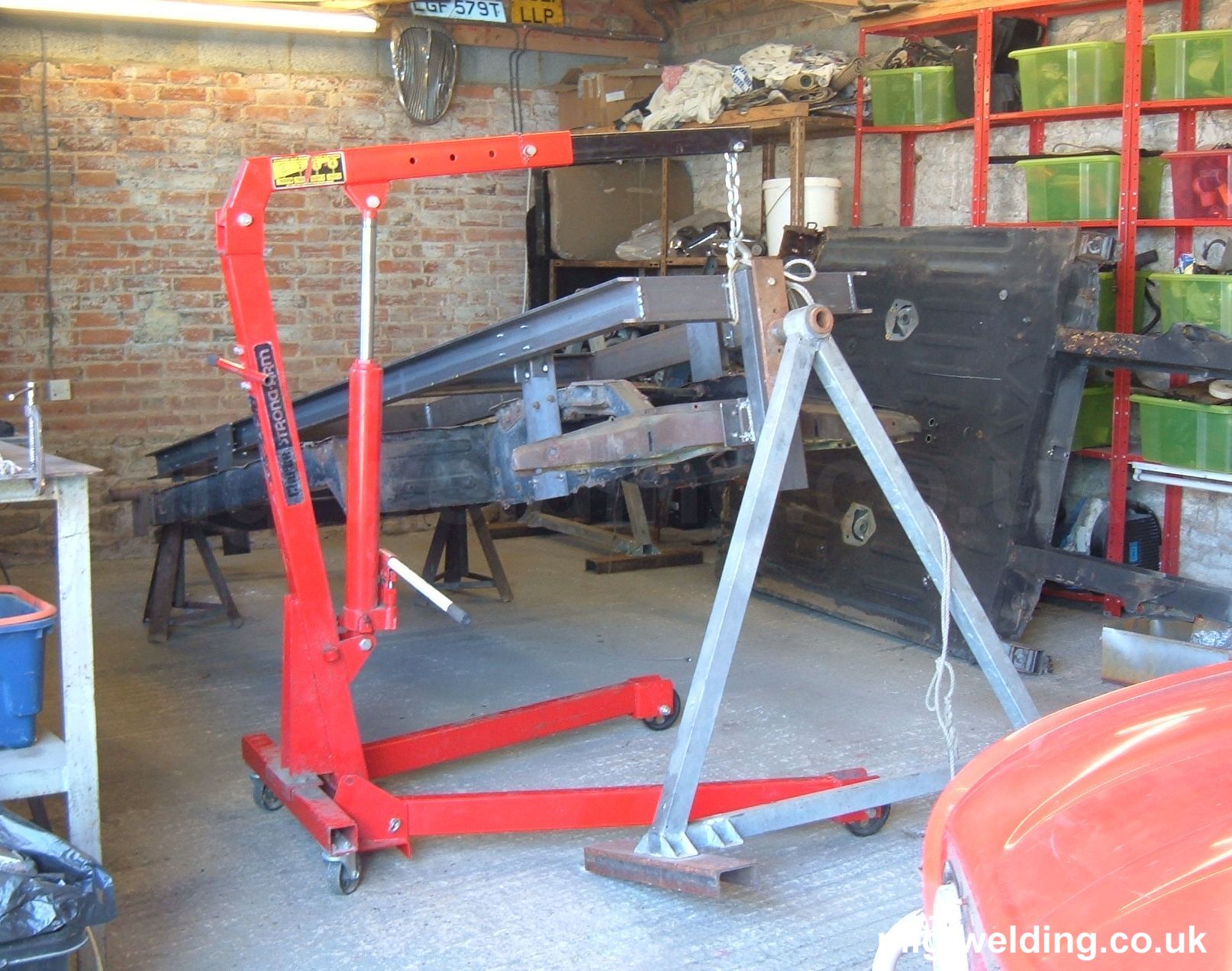
A big advantage of the jig is it allows the chassis to be mounted on A frames. I'd considered building a body roller in the past, but rollers that bolt to the wheels or to front and rear bumper mountings rely on chassis stiffness and a common repair for these cars is to cut out and replace a large section of rear chassis.
This is where the lack of torsional stiffness will be a problem. My plan is to rotate the chassis so the jig is level, and use the red wine level gauge to check for twist during any major repairs.
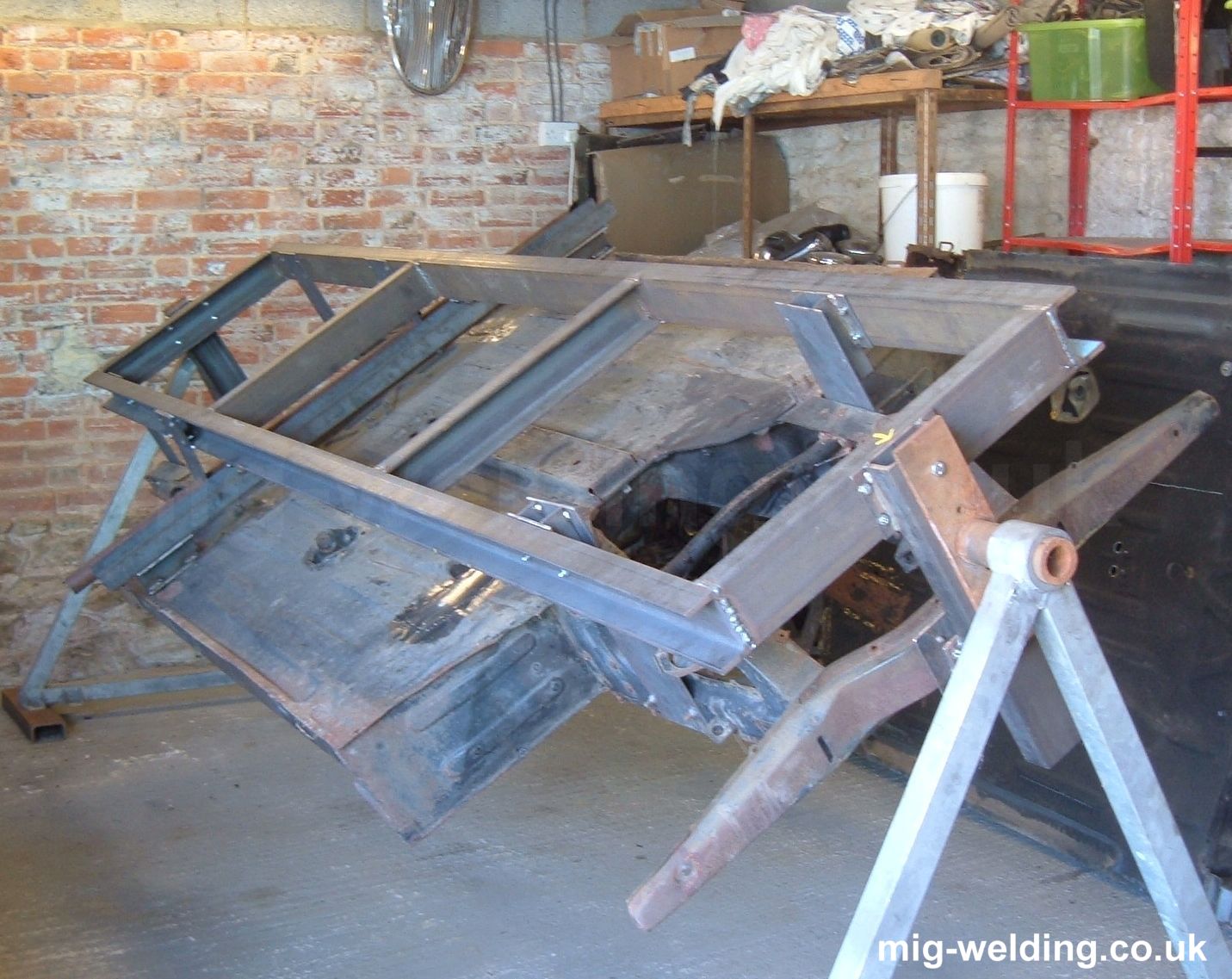
I was given the 'A' frames, but they should be reasonably easy to make up. Two very close fitting pieces of thick tube make up the bearing, and the friction between the two locate the chassis jig well enough to work on.
The tube connected to the jig passes through a hole in the mounting plate, and is welded on the rear of that plate.

'A' frames with built in jacks are available for use in body rollers, but an engine hoist can just as easily be used to lift the chassis and jig onto the 'A' frame. The frame is far too high for a trolley jack and axle stands to be used safely.
Building the jig cost around £100 in materials and another £100 to have the C section cut out and delivered. Construction time was probably around 50 hours (with a high proportion of the time spent setting up and measuring).
The jig was a very satisfying project and I'm quite pleased with the result. I've even compromised the fine tolerances by adding a coat of paint to make it look pretty.

If anyone is seriously interested in making a jig to position Renault 4 chassis parts the dimensions can be found on https://www.renault4.co.uk/chassis-jig-dimensions.htm


