You are using an out of date browser. It may not display this or other websites correctly.
You should upgrade or use an alternative browser.
You should upgrade or use an alternative browser.
wire feed failure - PCB E0788.1 - Oerlikon machine
- Thread starter FrankH
- Start date
Assuming that the circuit diagram in Post #6 of this thread is more-or-less applicable to your newer PCB:Have the PCB on my desk and the welder is at home. So powering up the PCB should be possible without the welder itself. I do have an adjustable PS here but only DC. To power up the board I would need 24V AC on Pins "IN" to the right. Correct?
Clarke 250T Blowing PCB fuse!
Hi guys, first post on here and I hope you can help. I have been given a Clarke 250T turbo to repair but it has me stumped. It operates perfectly at settings 1-4 but any higher the motor appears to stall and the PCB 5A fuse blows like a dead short? The owner replaced the motor after the wire...
www.mig-welding.co.uk
Sending 26v AC from an external supply into the PCB is OK, and I assume you have measured the same AC voltage on the secondary of the auxiliary transformer in the welder?Input 26V AC (same as from Welder) which should be fine when rated 24V, correct?
LED4 lights up. When shortening the trigger posts (Pin 5 and 6) LED3 comes up and the relay buzzes. Assume a missing load of some kind.
Rectifier WL02 output measured is 32,7V DV.
Diode 1N4001 to left of the rectifier gives same result (0,6V) from both polarisations. Unsoldered it and tested good. Replaced it (using IN4004) and got the same result when soldered in. So this must be by design.
Both black caps on the top left just over the rectifier are pretty warm.
Found a presumably faulty solder joint at the 2.2J250 cap. Reworked it.
NOW PCB is back in the machine and I get a click and an arc every time I press the trigger. BUT yet I don't get wirefeed. TBC I'd say.
When closure of the torch trigger switch is simulated, the 24v relay should simply "click" closed; it should not buzz. The only load that a relay has is current through the contacts, and the operating coil does not know or care about that.
Seeing about 33v DC after rectification of a 26v AC supply implies that there are smoothing capacitors, which raise the voltage from RMS towards the peak value ( x 1.414 ).
As voipio wrote in Post #12, that 1N4001 diode is wired across the relay coil, to suppress reverse voltage spikes induced when the relay is de-activated.
Capacitors should never get warm. You could check them for short-circuits, but may have to remove them from the rest of the circuit on the board to do this. There is a 220 Ohm wirewound resistor nearby which may be getting warm.
As Hutcho suggested, the "On" time of the relay may be influenced by the variable Spot timer. The On/Off switches on the back of timer potentiometers have been known to fail.
With the PCB back in the machine, does the contactor close every time you press the torch trigger? Do you get welding voltage ( from about 15 to 30 v DC ) between the MIG wire and the work return cable?
Power for the wirefeed controlled rectifier comes from a separate winding on the main welding transformer, via the two blue wires on Pins 1 and 2 of the 6-pin board connector.
Hello Hutcho, yes it's off and I removed the switch from the equation by unsoldering one of the two white wires that sit on the back of the potentiometer.Don’t suppose you have the spot timer on at all - just a thought
Assuming that the circuit diagram in Post #6 of this thread is more-or-less applicable to your newer PCB:
the tags marked "IN" and "OUT" to the right are for AC power that feeds the small on-board transformer, and for the relay-switched output to the coil of the contactor. It is possible that in your case "IN" is the low-voltage AC from the secondary of the off-board auxiliary transformer, bottom left under the contactor. You could trace the wires from the secondary of that transformer to the board, or trace the tracks on the board from the two AC inputs on the small circular rectifier ( marked with "~" ).Clarke 250T Blowing PCB fuse!
Hi guys, first post on here and I hope you can help. I have been given a Clarke 250T turbo to repair but it has me stumped. It operates perfectly at settings 1-4 but any higher the motor appears to stall and the PCB 5A fuse blows like a dead short? The owner replaced the motor after the wire...www.mig-welding.co.uk
Sending 26v AC from an external supply into the PCB is OK, and I assume you have measured the same AC voltage on the secondary of the auxiliary transformer in the welder?
When closure of the torch trigger switch is simulated, the 24v relay should simply "click" closed; it should not buzz. The only load that a relay has is current through the contacts, and the operating coil does not know or care about that.
Seeing about 33v DC after rectification of a 26v AC supply implies that there are smoothing capacitors, which raise the voltage from RMS towards the peak value ( x 1.414 ).
As voipio wrote in Post #12, that 1N4001 diode is wired across the relay coil, to suppress reverse voltage spikes induced when the relay is de-activated.
Capacitors should never get warm. You could check them for short-circuits, but may have to remove them from the rest of the circuit on the board to do this. There is a 220 Ohm wirewound resistor nearby which may be getting warm.
As Hutcho suggested, the "On" time of the relay may be influenced by the variable Spot timer. The On/Off switches on the back of timer potentiometers have been known to fail.
With the PCB back in the machine, does the contactor close every time you press the torch trigger? Do you get welding voltage ( from about 15 to 30 v DC ) between the MIG wire and the work return cable?
Power for the wirefeed controlled rectifier comes from a separate winding on the main welding transformer, via the two blue wires on Pins 1 and 2 of the 6-pin board connector.
Hello eddie, first of all MANY THANKS for your help and sharing off your profound knowledge!
No luck today:
* unsoldered one of the two white wires on the back of the spot welding timer to take this switch out of the equation and (like the day before) pressed the trigger.
* main contactor "pulled on" each and every time.
* I can also confirm that I got an arc but NO wirefeed. -> So far "welding" part seemed to be fine.
-> All of a sudden "trigger press action" stopped and now I am back where we started... press trigger, no nothing. Feels like a thermal issue...
* no nothing is not exact. The PCB is powered and LEDs light up as before. They are connected to the plug pretty direct so pressing the trigger triggers LED L3 (pin 5) , L4 (pin 6) and L5 (to pin 1) light upon power on whilst L2 (pin 4) stays off. -> so this should tell us that the torch trigger itself works and the board is not even triggering the feed motor. Correct?Hello eddie, first of all MANY THANKS for your help and sharing off your profound knowledge!
No luck today:
* unsoldered one of the two white wires on the back of the spot welding timer to take this switch out of the equation and (like the day before) pressed the trigger.
* main contactor "pulled on" each and every time.
* I can also confirm that I got an arc but NO wirefeed. -> So far "welding" part seemed to be fine.
-> All of a sudden "trigger press action" stopped and now I am back where we started... press trigger, no nothing. Feels like a thermal issue...
* checked the white rectangular 2.2µF condenser because it's housing has a little "burn spot" if you like on the outside of it's plastic housing but it looks like that came "from outside not from inside". Unsoldered it and measured 2.25µF.
* the next transistor in line I found is a darlington ZTX 601 left of the blue 220µF (left of WL02 rectifier). I read about the test proceedure and assume I'd have to unsolder it. Unfortunately they are a bit difficult to source here. So I wait for your input first.
Last edited:
Hello eddie49,
* I renewed some joints, transistors and diodes but didn't get any further
* in the machine the PCB didn't do anything really new. So I tipped/ticked on some parts with a srewdriver and uups after tipping on the condenser I mentioned at first I got the main contactor pulling again!
* looks like an intermittent or somehow "mechanical" fault there. I unsoldered the condensers check them and they where ok on the desk... Just ordered new ones and will update the thread asap
I unsoldered all three and all tested good. I soldered them to board and think I did that right. Nothing changed to behaviour in the machine. So before and after soldering the condensors it was all the same. It changed when ticking on one but I can't say which one exactly.
I'll replace them anyway and we will see probably next week.
I'll replace them anyway and we will see probably next week.
The capacitors appear to be part of the 24 - 26v AC supply coming in on Pins 1 and 2 from the external medium-sized transformer, which replaces the small on-board transformer that is used on other versions of this board. I do not have photos of both sides of your board so I cannot trace the exact wiring. The rectangular "2.2J250" component looks like a metallised-film/polypropylene mains noise filter capacitor, a "WIMA-type" capacitor, and these often fail.
As Hutcho pointed out, the Spot Weld Timer circuit, which holds the relay on for a preset, variable time after the torch trigger switch is pressed, does play a part in the reliable on/off operation of the relay. Do you ever use this Spot feature? If not, then one way to bypass the intermittent relay On/Off problem would be to alter the circuit so that the 24v relay is simply switched directly by the torch trigger. Many hobby-level welders do this, with the relay coil, at 12v or 24v DC, switched directly by the Eurotorch trigger.
The existing circuit has the trigger switch wires on Pins 5 and 6, then some debounce components and the LED indicators, the Spot timer, the ZTX601 NPN Driver transistor, and the relay coil. The ZTX601 is a 160v, 1A, 1W component, available on eBay UK. It is in a TO-92 case outline, so when looking at the flat face, the pins from the left are Emitter, Base, Collector. Datasheet here:
At rest, there will be about 20 volts across the transistor from the Collector to the Emitter. As an NPN transistor, it will conduct when the Base goes positive with respect to the Emitter. When conducting, the voltage across it from the Collector to the Emitter will drop to almost zero ( like a closed switch ), and that voltage will then go to the relay coil and operate the relay. By monitoring the rise in Base voltage, with respect to the Emitter, you can see if the transistor is being enabled into conduction every time the torch trigger is pressed. Then checking the falling Collector to Emitter voltage will confirm if the transistor is actually going into conduction.
Hello Eddie,The capacitors appear to be part of the 24 - 26v AC supply coming in on Pins 1 and 2 from the external medium-sized transformer, which replaces the small on-board transformer that is used on other versions of this board. I do not have photos of both sides of your board so I cannot trace the exact wiring. The rectangular "2.2J250" component looks like a metallised-film/polypropylene mains noise filter capacitor, a "WIMA-type" capacitor, and these often fail.
As Hutcho pointed out, the Spot Weld Timer circuit, which holds the relay on for a preset, variable time after the torch trigger switch is pressed, does play a part in the reliable on/off operation of the relay. Do you ever use this Spot feature? If not, then one way to bypass the intermittent relay On/Off problem would be to alter the circuit so that the 24v relay is simply switched directly by the torch trigger. Many hobby-level welders do this, with the relay coil, at 12v or 24v DC, switched directly by the Eurotorch trigger.
The existing circuit has the trigger switch wires on Pins 5 and 6, then some debounce components and the LED indicators, the Spot timer, the ZTX601 NPN Driver transistor, and the relay coil. The ZTX601 is a 160v, 1A, 1W component, available on eBay UK. It is in a TO-92 case outline, so when looking at the flat face, the pins from the left are Emitter, Base, Collector. Datasheet here:
At rest, there will be about 20 volts across the transistor from the Collector to the Emitter. As an NPN transistor, it will conduct when the Base goes positive with respect to the Emitter. When conducting, the voltage across it from the Collector to the Emitter will drop to almost zero ( like a closed switch ), and that voltage will then go to the relay coil and operate the relay. By monitoring the rise in Base voltage, with respect to the Emitter, you can see if the transistor is being enabled into conduction every time the torch trigger is pressed. Then checking the falling Collector to Emitter voltage will confirm if the transistor is actually going into conduction.
thank you very much for your Input. I attached pictures of both sides of the PCB. Hope this can help others with a similar PCB too.
I replaced only the three caps and the 2,2µF WIMA you mentioned with no real success. I press the trigger and nothing happens AT FIRST. I than tick on the (now red) 2.2 cap OR on the heatsinks of the thyristors and get the main welding contactor to click (incl. arc).
SO I assume there is some cold joint or another part that is mechanically sensitive.
One detail obeserved is that the new relay sometimes buzzes. So there might be some fault in the supply route for the relay coil.
I hope I have time by the weekend to replace more parts. I ordered most of them except the Darlington ZTX601 which was not in stock... damn... I will get me two of these asap.
And I will make better pictures and overlay them this weekend. Have to set up my camera and lights first.

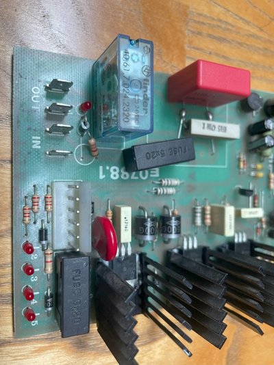
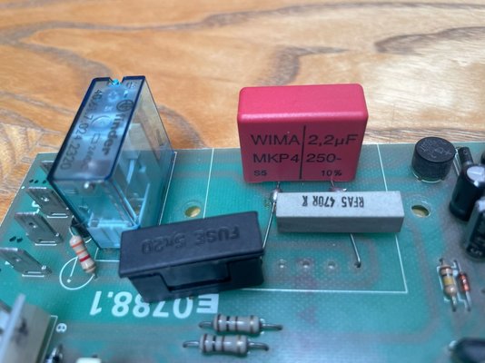
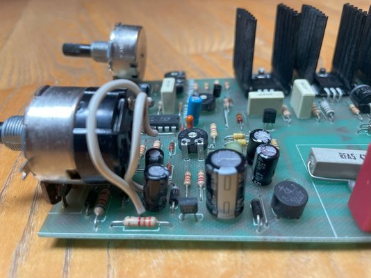
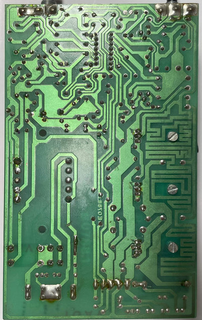
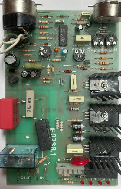
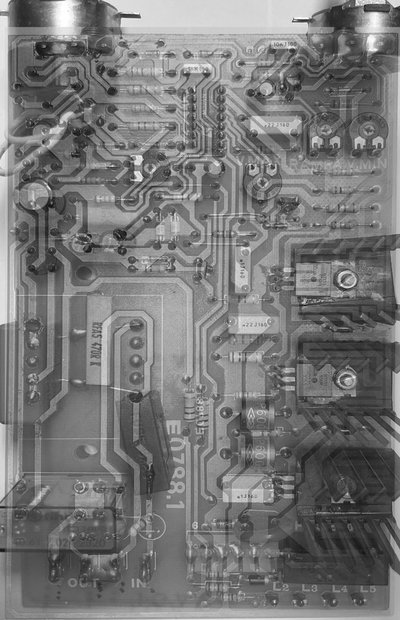
Ok I can see the fuse is bridging the track now - sorryIs this track cut ? Also has the relay got enough solder ? I can’t tell from my phone .
View attachment 457575
To check for an intermittent contact failure, you could try gripping the left & right or the top & bottom edges of the PCB with two hands and twisting the board.
The "buzzing" relay - does it sound like 50 or 100 Hz ? If so, maybe something is shorting or dropping half of the AC cycle in the supply from the auxiliary transformer.
If the buzzing is slower than that, it could be a failure in the Spot Timer circuit.
You could remove the ZTX601 Darlington pair transistor which drives the 24v relay, and replace it with a pushbutton switch that joins the track locations for Collector to the Emitter. Pushing the button would simulate the transistor conducting, and the relay should pull in reliably and consistently.
I replaced the Darlington transistor and the rectifier that came in today. Didn't resolve the issue.To check for an intermittent contact failure, you could try gripping the left & right or the top & bottom edges of the PCB with two hands and twisting the board.
The "buzzing" relay - does it sound like 50 or 100 Hz ? If so, maybe something is shorting or dropping half of the AC cycle in the supply from the auxiliary transformer.
If the buzzing is slower than that, it could be a failure in the Spot Timer circuit.
You could remove the ZTX601 Darlington pair transistor which drives the 24v relay, and replace it with a pushbutton switch that joins the track locations for Collector to the Emitter. Pushing the button would simulate the transistor conducting, and the relay should pull in reliably and consistently.
Twisting the PCB was a very good hint!
A slight twist and the main contactor pulls in while keeping the trigger pressed.
BUT yet I never got the wire feed motor to start so I guess the part that needs "the twist" or has a kind of bad joint must be in the section of the circuit that starts the wire feed motor.


