SirDick Diodenob esquire
Member
- Messages
- 192
Having problems with wire speed , used a stop watch and its doing 1.4m/minute , using 0.8mm wire and will not adjust , I am thinking thats good for nothing as the range on the front plate shows 3m to 15m maximum/minute ?
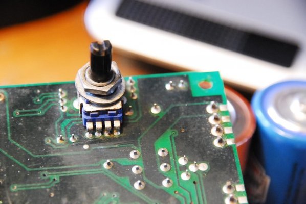
The pcb board is made by Cigweld dated 10 July 97 type X4811 and have been unable to find a circuit diagram for it . The board is double sided approx 7x10cm and controls the gas valve/contactor coil/fan as well as speed control . In addition to the speed pot there is a 10k ohm pot for burn back . I am thinking the speed control pot has failed but cannot identify it as unlike the burnback pot it has no markings , nearest I can find in the RS catalogue is 263-3135 which looks the same but only goes down to 10k ohm but in addition am not sure of the internal wiring of the pot . I am assuming from the RS catalogue that its a single shaft 11mm ( snap in ? why is it called snap in ? ) . Assuming pin 1 is far left and pin 4 far right is a dummy then the wiper should be pin 2 ? I am getting 2.7k ohm accross 1 and 3 and 2.8k ohm on 1 and 2 no matter what position shaft is in , there could be components in parallel on the other side of the board causing this reading and maybe it could be a 10k ohm pot ? I am planning to short out 1 and 2 to see if it goes to maximum speed , would this be ok or might damage the integrated circuits if I have got it wrong ?
The pcb board is made by Cigweld dated 10 July 97 type X4811 and have been unable to find a circuit diagram for it . The board is double sided approx 7x10cm and controls the gas valve/contactor coil/fan as well as speed control . In addition to the speed pot there is a 10k ohm pot for burn back . I am thinking the speed control pot has failed but cannot identify it as unlike the burnback pot it has no markings , nearest I can find in the RS catalogue is 263-3135 which looks the same but only goes down to 10k ohm but in addition am not sure of the internal wiring of the pot . I am assuming from the RS catalogue that its a single shaft 11mm ( snap in ? why is it called snap in ? ) . Assuming pin 1 is far left and pin 4 far right is a dummy then the wiper should be pin 2 ? I am getting 2.7k ohm accross 1 and 3 and 2.8k ohm on 1 and 2 no matter what position shaft is in , there could be components in parallel on the other side of the board causing this reading and maybe it could be a 10k ohm pot ? I am planning to short out 1 and 2 to see if it goes to maximum speed , would this be ok or might damage the integrated circuits if I have got it wrong ?