You are using an out of date browser. It may not display this or other websites correctly.
You should upgrade or use an alternative browser.
You should upgrade or use an alternative browser.
Single phase motor wiring/connection diagrams
- Thread starter MattF
- Start date
MattF
Forum Supporter
- Messages
- 18,460
- Location
- South Yorkshire
brightspark
Member
- Messages
- 41,357
- Location
- yarm stockton on tees
anyone know what starting cap for a 1hp gryphon motor 

Sorry to jump on this post.
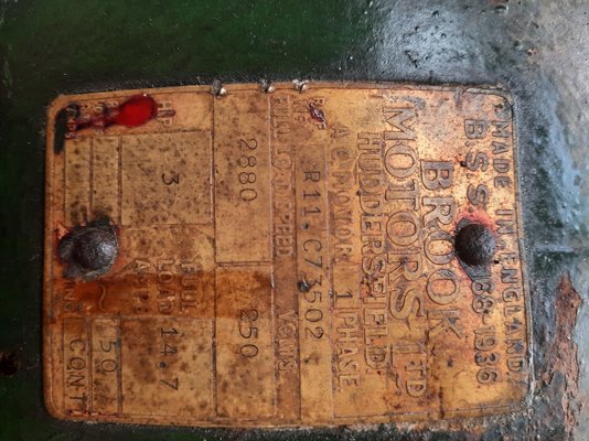
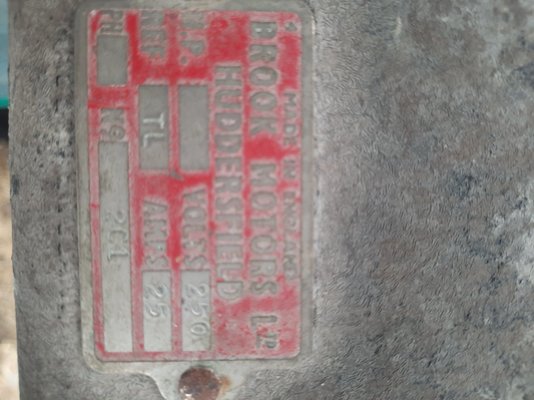
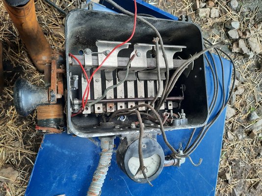
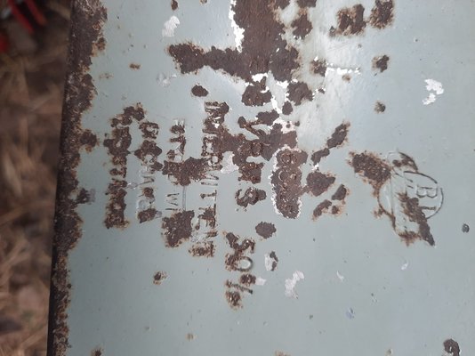
I have a 3HP single phase 2.2kw 15A 2800rpm Brook Motor from about 1950 with a separate starting control box and capacitor.
It is used to run a grain bruiser (mill).
I bought it blind from a farm however it had been lying disconnected so couldn't see it wired up. Additionally, the seller had cut the wires from the motor to the control box, as well as disconnecting all wires from terminals, so it's a headscratcher. I have a friend who is great with these sort of things but it's from an era before he was born (and me!)
So in a nutshell, it is single phase. It has 2 cables coming from mains (earth all external/separate) to the control box.
The control box has a manual handle which flicks between down=START middle=OFF or up=RUN. The handle moves a contactor which makes different contacts depending on position. There appears to be an adjustable overload 'bolt' style switch which pushes the manual handle out of run. The control box also features an ammeter.
So from the control box, 1 cable goes up to the capacitor, which is a couple of kg at least Nd marked 60(u)F and 250v vrms 50%
The return cable from starting capacitor routes through control box and directly back out towards the motor terminals, bypassing the contactors.
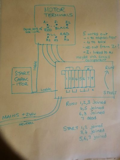
There are a further 4 cables from the contactor/control box out to the motor terminals. Annoyingly all cut.
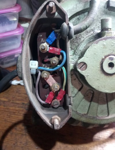
The motor has 6 terminals.
Top row A1 Z1 Z2
Below. A2 A3 A4
there is no flex leading out from Z1. 1 flex leaves each other terminal towards snip in wire. Annoyingly all black.
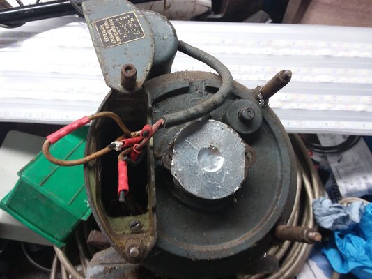
A1 is connected to Z1 using something heatshrinked (maybe a very small component or just cable, can't see) and Z1 otherwise has no outward connection.
All 6 appear to have wires going into the motor. Z1 Z2 are black. Other 4 red.
Back in the control box at other end of wires...
The contactor has 8 terminals, plus a small additional one which I assume is for earth as the contactor doesn't reach it in either position.
There are 2 mains wires, 1 capacitor wire and 4 motor wires (total 7)
Obviously when the handle is set to off no cOntact is made.
In START,
terminal T1 and T2 are joined.
T3 and T4 are joined.
T5, T6 and T7 are joined.
I've named them left to right. They are not labelled.
In RUN
T1, T2, T3 are joined.
T4 and T5 are joined.
T6 and T8 are joined.
So clearly something going on with 7 and 8 being substituted - I would hazard a guess that 7 goes out to starter capacitor?
Reading other forums it looks like I have a 2 pole motor and possibly that the starter position would run the 2 'run' poles in series as well as the starter Z coil in ?parallel?, and then when I fling the handle the other way, the capacitor is deprived of its neutral (T7?) And the 2 run coils switch to parallel.
I am not an electrician, my friend is but this is just too old for him to figure out.
The closest I could find to a manual says that the starter will use 150% full load current (15A×1.5=22.5A) with 50% torque.
The question is this, which motor terminal to which contactor terminal?
Thanks in advance!


Guineafowl
Member
- Messages
- 1,454
- Location
- Nairn
Oof. @daniel123 I hope you take some time to make a voodoo doll of whoever pulled all the wires off.
I’ve drawn what I think are the desired states in each switch position, assuming a series-start, parallel-run for the main winding A. The “Link” might be an NTC thermistor for inrush limitation to the start (Z) winding.
On the right, possible connections for the switch. I’m not sure about 7 and 8, but at least it has 4 wires to the motor and one to the cap, and corresponds with the two on states. Maybe the start cap/Z winding combo is somehow shorted in the run state, to discharge the cap.
I concur with @Guineafowl and are likewise unsure about 6-7-8 in the run position. If this is for discharging the cap I'd expect to see a resistor to dissipate the stored energy rather than just a short.
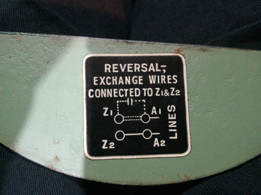
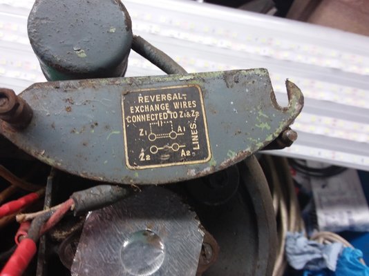
To reverse direction (should you want to) reverse the connections to Z1 and Z2.
The ammeter would be in series with the supply input.
I'd want to check or replace the capacitor if it's 70 years old.
I'd also check the winding resistances to see A1 to A2 and A3 to A4 are about the same.
We're assuming that A1 and A3 are the starts of the windings so the magnetic field from both coils assists rather than cancels.
Good luck & report back how it goes.
Hello! Sorry I didn't see that anyone had replied (only joined forum to ask question!)Oof. @daniel123 I hope you take some time to make a voodoo doll of whoever pulled all the wires off.
I’ve drawn what I think are the desired states in each switch position, assuming a series-start, parallel-run for the main winding A. The “Link” might be an NTC thermistor for inrush limitation to the start (Z) winding.
On the right, possible connections for the switch. I’m not sure about 7 and 8, but at least it has 4 wires to the motor and one to the cap, and corresponds with the two on states. Maybe the start cap/Z winding combo is somehow shorted in the run state, to discharge the cap.
View attachment 457325
Your diagram makes good sense even to me a newbie. Re 7 and 8, there is the ammeter and there is also a 'programmable' (i wonder whether this equipment predates that word?) High load cut out that physically bashes the handle to stop. There would also have been optional extras such as fans, grain movement augers so maybe they sat at the right of the control board...
I shall put this to my sparky and see what he has to say- thanks ever so much!
Re the 'link', can a thermistor be grain or rice sort of size? And was that the case in 19oatcake?
Re voodoo dolls, he already works a permanent night shift so no action required
//Hi! See above reply to GF, maybe there is a wee thermistor bolted between a1 and z1? I did certainly read somewhere that some types of motor you just deprive cap of neutral, but i'm a layman.I concur with @Guineafowl and are likewise unsure about 6-7-8 in the run position. If this is for discharging the cap I'd expect to see a resistor to dissipate the stored energy rather than just a short.
No need so far as I knowTo reverse direction (should you want to) reverse the connections to Z1 and Z2.

What so + to terminal 1 and - to t5? This would show a reading (perhaps of zero?) even when switch in off position? OR T2/T5 to prevent that?The ammeter would be in series with the supply input.
it is marked 60(u)F and was reading 4.5/45/450, something like that, from memory. No idea what scale sparky was using. Can verify myself if I can fathom out correct multimeter setting.I'd want to check or replace the capacitor if it's 70 years old.
Sparky did soI'd also check the winding resistances to see A1 to A2 and A3 to A4 are about the same.

yeah? Haha.We're assuming that A1 and A3 are the starts of the windings so the magnetic field from both coils assists rather than cancels.
Thanks Martin, much appreciatedGood luck & report back how it goes.

Guineafowl
Member
- Messages
- 1,454
- Location
- Nairn
I’d expect an NTC for a start winding to be bigger than that. Leave well alone if it works!
(Note for mods: I PM’d daniel123 to tell him there were replies. Some new users seem to think email notifications are opt-out rather than opt-in. It might explain some of the one-post wonders.)
(Note for mods: I PM’d daniel123 to tell him there were replies. Some new users seem to think email notifications are opt-out rather than opt-in. It might explain some of the one-post wonders.)
I can get a pic of 'link' - it may just be a wire!
Yes, I signed up, didn't get owt via email to confirm signup had happened(it said awaiting confirmation on here) or any email to say any replies had been posted.
Just one this morning to say you had messaged
Ta
Yes, I signed up, didn't get owt via email to confirm signup had happened(it said awaiting confirmation on here) or any email to say any replies had been posted.
Just one this morning to say you had messaged
Ta

