You are using an out of date browser. It may not display this or other websites correctly.
You should upgrade or use an alternative browser.
You should upgrade or use an alternative browser.
Sealey Supermig 180/1 PCB photo needed
- Thread starter peterbol
- Start date
Hello ( or Bonjour ), and welcome to the Forum!
The photo in Post #2 of this earlier thread:
and this repair service:
both show a board with modern surface-mount ( SMD ) components. Your board must be an older version, using traditional through-hole components?
Does the board itself have any part numbers printed on it?
A photo of your board may help, especially if we end up having to reverse-engineer the circuit to guess the resistor value.
Have any other components failed, for example power semiconductors that shorted and caused the resistor to blow?
The photo in Post #2 of this earlier thread:
Sealey 180 supermig v3
My uncle has asked me to look at his Sealey 180 V3 but it looks like someone has been in there playing as some of the wiring looks (from the supplied schematic from sealey) to have been messed around with. One quick question, there is a sort of ferrite ring bolted through the base with red and...
www.mig-welding.co.uk
Pardon our interruption...
www.ebay.co.uk
Does the board itself have any part numbers printed on it?
A photo of your board may help, especially if we end up having to reverse-engineer the circuit to guess the resistor value.
Have any other components failed, for example power semiconductors that shorted and caused the resistor to blow?
Last edited:
Hi eddie, thanks for the reply
Yes its the older one, bought it new sometime in the 90s..Haven't used it in 10 years or so as gas here is very expensive and you have to buy the bottle..
No part numbers on the pcb..
I plugged it in as I was considering changing the polarity to try flux core and found the wire feed motor wasn't working, pulled the motor off and tested it on 12 volt, works fine, but had no power getting to it from pcb..
After coming across a post on here I've tested the auxillary transformer and it reads ok, and the wire will arc to the earth clamp, so all seems ok that side..
Just no power to motor..
After checking and cleaning and whilst pulling the trigger for a few seconds I noticed smoke from a resistor (bottom right of photo) near a transistor( bottom far right behind the plate with rivet in) which I'm now wondering could be the problem..
Deep dive into electronics here, but would like to learn more lol..
I saw the ebay ad for repair, but i'm loathe to send anything to UK now after breakshit..(Post office here like to sting you for admin fee, even if there is no import tax to pay..And stuff can end up hiding in the customs shed for weeks as well )
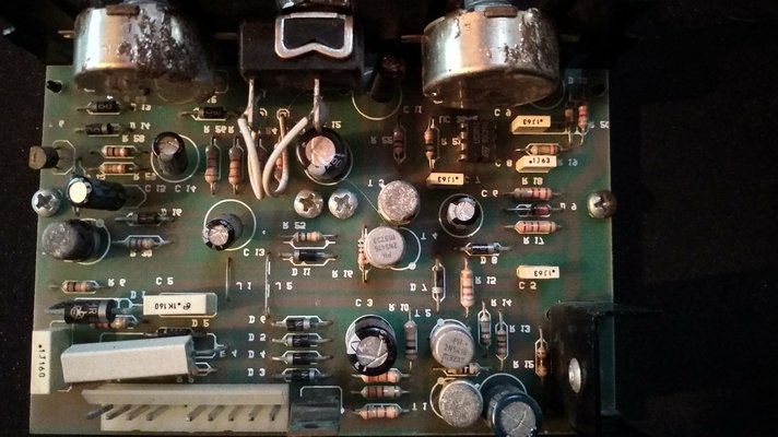
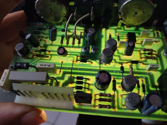


Sealey liked to change the design of that pcb regularly, I had the same problem as you on my Supermig 180/2 & I couldn't find a photo or diagram online of a matching pcb. I traced the problem to the mini step down transformer on the board & replaced that.
Regarding running gasless wire, there's a thread somewhere on here about somebody trying to run gasless wire on a welder not designed for it (maybe a Sealey?). They tried swapping the polarity but that caused some issues (I think the feed motor ran backwards).
Regarding running gasless wire, there's a thread somewhere on here about somebody trying to run gasless wire on a welder not designed for it (maybe a Sealey?). They tried swapping the polarity but that caused some issues (I think the feed motor ran backwards).
That's interesting, don't suppose you can see that step down on this board can you?Sealey liked to change the design of that pcb regularly, I had the same problem as you on my Supermig 180/2 & I couldn't find a photo or diagram online of a matching pcb. I traced the problem to the mini step down transformer on the board & replaced that.
Regarding running gasless wire, there's a thread somewhere on here about somebody trying to run gasless wire on a welder not designed for it (maybe a Sealey?). They tried swapping the polarity but that caused some issues (I think the feed motor ran backwards).
This thread has an overall circuit diagram for the first version of the Supermig 180 :
It shows a PCB with a 10-pin connector, which does correspond to yours.
The auxiliary ( step-down, or standby ) 24v transformer is mounted separately, not on the board. If the welder switches on and the trigger enables the arc via the contactor ( relay ) - and the gas valve too - then the 24v supply from that transformer must be present.
It is possible that the power transistor on the black heatsink at the lower right-hand corner of the board drives the wirefeed motor, and it has a short on the Base connection, and that caused the nearby resistor to burn. I think it is R15. The white silkscreen printing seems to be partially in mirror-image ...?
Could you note the part number of that power transistor, and also please post a photo of the track side of the board?
Sealey Supermig 180/1 Wiring Diagram
Hi, Attached is a wiring diagram for the Sealey SuperMig 180/1. I obtained it from Sealey Support as I had no joy searching the Internet for one. Thought it would be useful posting it on here. Dave
www.mig-welding.co.uk
The auxiliary ( step-down, or standby ) 24v transformer is mounted separately, not on the board. If the welder switches on and the trigger enables the arc via the contactor ( relay ) - and the gas valve too - then the 24v supply from that transformer must be present.
It is possible that the power transistor on the black heatsink at the lower right-hand corner of the board drives the wirefeed motor, and it has a short on the Base connection, and that caused the nearby resistor to burn. I think it is R15. The white silkscreen printing seems to be partially in mirror-image ...?
Could you note the part number of that power transistor, and also please post a photo of the track side of the board?
Yes that's the diagram for this machine, the auxillary 24 volt transformer is working and there is an arc when the trigger is pressed, I haven't tested the gas valve..
The printing is indeed in mirror image in a few places across the board and the burnt out resistor is R 12 next to the transistor and heat shield, the transistor is a BUV46, bottom left corner on the track side..
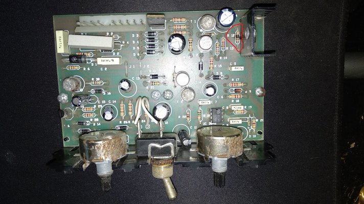
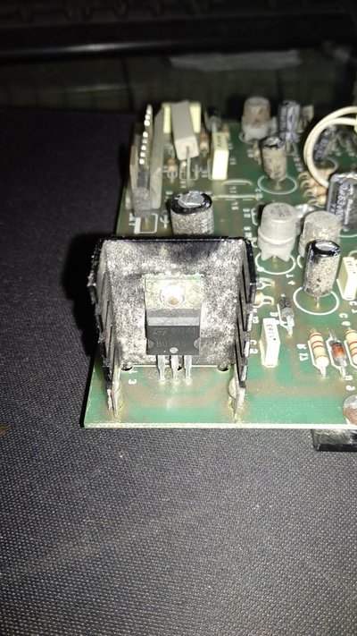
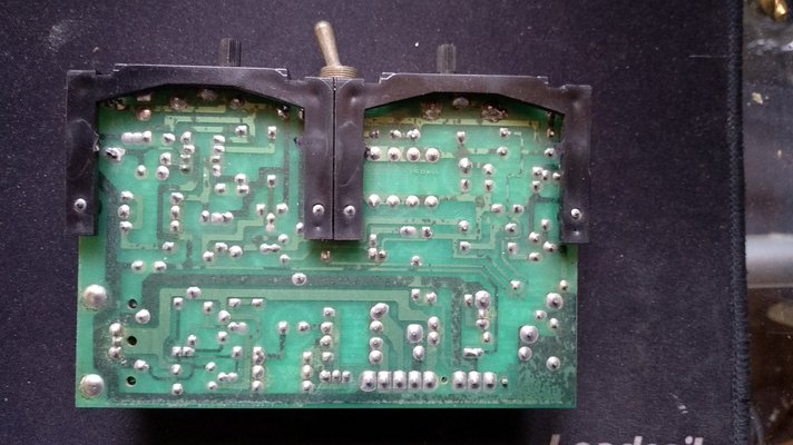
The printing is indeed in mirror image in a few places across the board and the burnt out resistor is R 12 next to the transistor and heat shield, the transistor is a BUV46, bottom left corner on the track side..


Thank you for the additional photos.
The BUV46 is an NPN power transistor, rated at 850v ( !! ) and 5 Amps. Looking at the tracks, the Emitter is linked to Pin 8 of the white connector, which goes to the Positive side of the wirefeed motor, so this transistor does drive the motor.
The burnt resistor R12 is connected from the Base to the Emitter. If there is an internal short from the Collector to the Base, the 24v supply will try to run the wirefeed motor via R12, which would explain the fault.
Could you please remove the BUV46 transistor and check it? This can be done with the "Diode Test" function on a digital multimeter, as described in this test procedure:
The suspect transistor does need to be tested rather than just replaced, because the fault may actually be earlier in the circuit, and so it would occur again.
Unfortunately we still do not know the value of resistor R12.....
With the transistor out-of-circuit, could you try measuring the present resistance of R12?
Hopefully a Forum member who has this version of the Sealey Supermig 180 will respond with a value for the resistor.
Thanks very much Hucho and Eddy
Ok I have a reading of 0050 when the transistor is in the DMM transistor tester, And when in diode mode im getting:
Base to Emitter OL
Base to Collector 0.34
Emitter to Base OL
Collector to Base 0.23
Collector to Emitter OL
Resistor 099.3 ohms
Ok I have a reading of 0050 when the transistor is in the DMM transistor tester, And when in diode mode im getting:
Base to Emitter OL
Base to Collector 0.34
Emitter to Base OL
Collector to Base 0.23
Collector to Emitter OL
Resistor 099.3 ohms
Thank you Hutcho. That makes R12 a 100 Ohm resistor, with 5% tolerance. The purpose is to bias the transistor "off" when there is no input signal turning it on. It seems like a very low resistance value for this purpose, I would expect from 1K to 10k, but even the burnt resistor is reading 99 Ohms, so it must be right....?Gold brown black brown
@Hutcho , if R12 is as low as 100 Ohms, it will show that reading, or slightly less, even when measured in-circuit on the board with other components in parallel with it, so if you get the chance, could you please measure yours to confirm the value?
The BUV46 transistor appears to be very broken. The Base to Emitter is open-circuit both ways, and the Base to Collector is short-circuit both ways, so it will have to be replaced with a new one. They are readily available in the UK :
Pardon our interruption...
www.ebay.co.uk
Pardon our interruption...
www.ebay.co.uk
Thank you Eddie for confirming the transistor is indeed broken, the resistor is an unknown to me as to how to calculate the value needed, as I said I'm on a deep dive here and currently consuming as much knowledge as I can from the ground up lol..
I shall order up the parts and replace..
Is there any other parts of the circuit or componants I should be looking at ?
I've tested all diodes and they all seem ok, although not sure how reliable it is to do that while they're in the board..?
I shall order up the parts and replace..
Is there any other parts of the circuit or componants I should be looking at ?
I've tested all diodes and they all seem ok, although not sure how reliable it is to do that while they're in the board..?
Thank you Hutcho. That makes R12 a 100 Ohm resistor, with 5% tolerance. The purpose is to bias the transistor "off" when there is no input signal turning it on. It seems like a very low resistance value for this purpose, I would expect from 1K to 10k, but even the burnt resistor is reading 99 Ohms, so it must be right....?
@Hutcho , if R12 is as low as 100 Ohms, it will show that reading, or slightly less, even when measured in-circuit on the board with other components in parallel with it, so if you get the chance, could you please measure yours to confirm the value?
The BUV46 transistor appears to be very broken. The Base to Emitter is open-circuit both ways, and the Base to Collector is short-circuit both ways, so it will have to be replaced with a new one. They are readily available in the UK :
Pardon our interruption...
www.ebay.co.ukPardon our interruption...
www.ebay.co.uk
If you test a component in-circuit and it shows the expected result ( e.g. a resistor value that is about right, a capacitor that is not short-circuit, or a diode that conducts one way and is open-circuit the other way ) then it can be assumed to be OK. If the result is wrong, it may the due to failure or because of other components in parallel, so then you would have to unsolder one end - or two/all for a transistor - and test again.Is there any other parts of the circuit or componants I should be looking at ?
I've tested all diodes and they all seem ok, although not sure how reliable it is to do that while they're in the board..?
The BUV46 transistor has definitely failed, and that has damaged resistor R12. Driving the wirefeed motor, that transistor has a tough life, and maybe it just died. However, it is possible that other faulty components earlier in the circuit sent too much Base current to that transistor, forcing it too hard into conduction, exceeding the power limit for the device, and causing it to short-circuit internally. There is a small chance that the new transistor may fail again.
Thanks Eddie, I've tested just about everything on the board now in situ and can't see anything majorly wrong.. From what I've read this looks like a pwm motor controller with what looks like an H-bridge, would that be a good guess do you think? I'm waiting on the parts from ebay which should be here next week and will update..I hoping for the best and expecting the worst ..!If you test a component in-circuit and it shows the expected result ( e.g. a resistor value that is about right, a capacitor that is not short-circuit, or a diode that conducts one way and is open-circuit the other way ) then it can be assumed to be OK. If the result is wrong, it may the due to failure or because of other components in parallel, so then you would have to unsolder one end - or two/all for a transistor - and test again.
The BUV46 transistor has definitely failed, and that has damaged resistor R12. Driving the wirefeed motor, that transistor has a tough life, and maybe it just died. However, it is possible that other faulty components earlier in the circuit sent too much Base current to that transistor, forcing it too hard into conduction, exceeding the power limit for the device, and causing it to short-circuit internally. There is a small chance that the new transistor may fail again.
Thanks again !!
(FIXED) Happy to report job's a good'n, changing the resistor and transistor have sorted the motor out and the welder's up n running again..Thanks very much for your help eddie49, Hutcho and Turbo, very much appreciated..Now off to find that post on swapping the polarity..

