You are using an out of date browser. It may not display this or other websites correctly.
You should upgrade or use an alternative browser.
You should upgrade or use an alternative browser.
Sealey 170/1 Voltage control switch
- Thread starter brading
- Start date
mike 109444
Member
- Messages
- 4,884
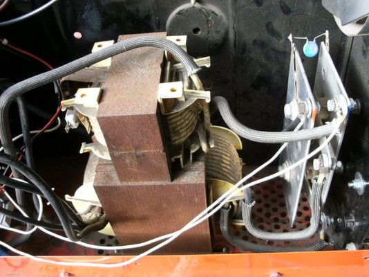
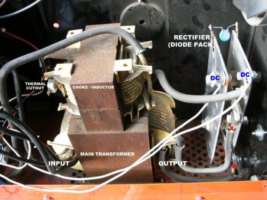
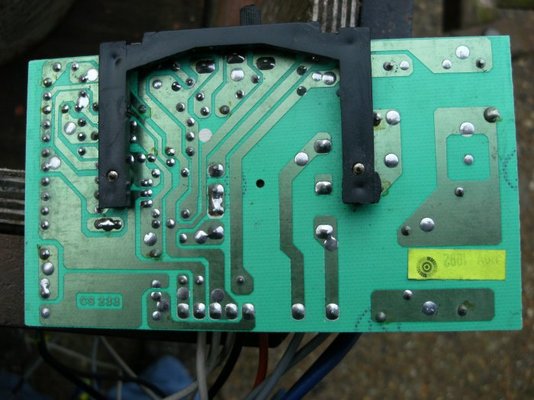
Paul I have marked up your pic, see below.
The AC (16ish to 28ish volts) output from the transformer goes to the diode pack. This converts it to DC for welding.
If you meter across X to X with meter set to AC.
If the AC is ok then meter across the DC to DC With meter set to DC!
When you start to wire up the rest the thermal cutout will need to be included to protect the welder from over heating.
If you want to check the thermal cutout then with meter set on ohms (0 to 200 range) when metering across it's two spade connectors you should see on meter 0:00 ohms or very close to this. If it meters as open circuit then it's duff (could have been the orignal fault!!!!)
Is there a third transformer ? may be much smaller than others 3" cube?
Hi Mike
Checked the thermal cutout switch and I get a reading of 00.00 ohms. With the wiring connected up as the Sealey diagram I only get very low AC voltage readings of just 4 volts or less. I took wire off of diagram terminal F2 and connected it to switch terminal L2 and got the following readings. On the AC side switch pos 1- 21v, pos 2 - 23v, pos 3 - 26v. pos 4 - 28v, pos 5 - 32v, pos 6 - 36v and on the DC side Pos 1 - 50v, Pos 2 - 51v, pos 3 - 62v, pos 4 - 65v, pos 5 - 81v, pos 6 - 86v. There is a small transformer mounted on the wire speed control board
Cheers Paul
mike 109444
Member
- Messages
- 4,884
Paul not sure if you are getting the measurements back to frount?
Would have expected to see the AC output of the transformer to be the readings you say you got on the DC reading! and vis-versa the AC.
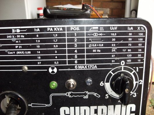
Somewhere on the welder should be a data plate/sticker showing the DC output saying something like 16v-30v. This would be the DC output.
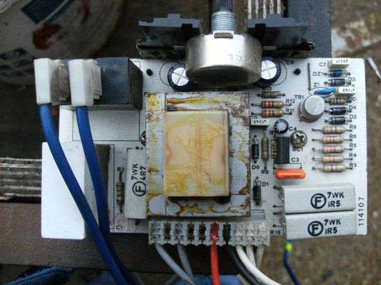
On the connectors (pcb connector or connections on pcb) marked F1 and F2 is there a fuse or relay (suspect from other diagram) its a relay.
What ou have done by connecting the F2 connector to the L2 connection is bypass the protection (fuse?) or control (relay?) on the pcb.
You have also bypassed the thermal cutout and probley the power feed to the fan!
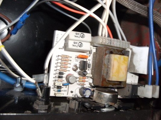
Do you have pic of the pcb both sides?
Still you are getting there....
Would have expected to see the AC output of the transformer to be the readings you say you got on the DC reading! and vis-versa the AC.
Somewhere on the welder should be a data plate/sticker showing the DC output saying something like 16v-30v. This would be the DC output.
On the connectors (pcb connector or connections on pcb) marked F1 and F2 is there a fuse or relay (suspect from other diagram) its a relay.
What ou have done by connecting the F2 connector to the L2 connection is bypass the protection (fuse?) or control (relay?) on the pcb.
You have also bypassed the thermal cutout and probley the power feed to the fan!
Do you have pic of the pcb both sides?
Still you are getting there....
Hi Mike
Found that the wires to and from the speed control board are mard as to where they should go so I wired the welder completely. Then I checked the AC and DC outputs on the rectifer with the torch trigger held on and got the following results. on the AC side switch position 1-21v, 2-23v, 3-26v, 4-28v, 5-32v, 6-36v and on the DC side switch position 1-19v, 2-20v, 3-23v, 4-24v, 5-27v, 6-31v. Which appear close to the info as on the data board if I understand it correctly. I then tried welding and it seemed okay though for some reason I had to have the wire speed fairly high on all settings and then some times it was not making the nice cracking sound normally heard when welding, just seemed more like burning. I have now found out that the torch is falling to bits and have to try to repair it.
Cheers Paul
mike 109444
Member
- Messages
- 4,884
Result then paul
You are correct with the data plate ie UoV coloum 18.5 to 31v.
Ref the wirefeed/speed If you can hookup your meter to the output for feed motor and when welding get someone to look at the reading. If it is a 24v motor then it should be in the range of 4 to 26vDC and stable. If not stable then could be there is a failing component or poor connection on pcb.
The problem with the change in weld during welding this would also be caused by the wire feed falling then returning or could be poor connections from choke to earth connection on front of machine or poor earth lead /connections.
mike 109444
Member
- Messages
- 4,884
Paul just thought could be the brushes in the motor. If you can get them out try blowing out the dust in the brush holders
Sealey 170/1 Votage control switch
Hi Mike
Many thanks for all your help so far. Not had a lot of time lately. I have been trying to sort my torch that was falling to bits with out success. Have bought another srcap welder with a euro torch which I am now going to fit to the machine. I now will now need to find info on how to wire it up to work both the motor and the gas solenoid. The scrap welder has a 24volt gas solenoid.
Cheers brading
mike 109444
Member
- Messages
- 4,884
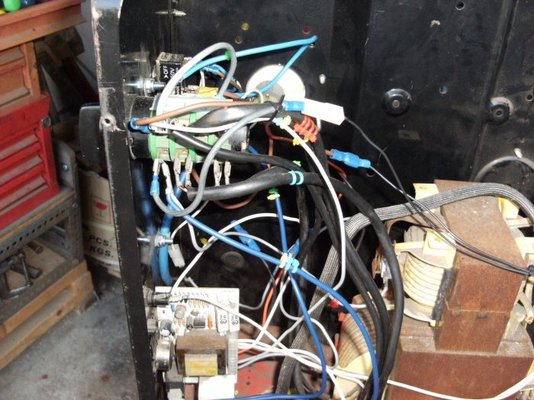
Hi Paul Thought you migh have fried yourself!!. Does your welder have the gas valve in the handle/tourch? If not then it should be easy enough to fit and wireup. Make sure you check/use any insulators that might be with the euro tourch and socket. Hopefuly Someone that has fitted one of the kit type euro tourch conversions may be reading this and still have the instructions (because what you are doing is much the same) and they may post them on this post. Looks like the frount of your machine has the hole already for a euro socket, just that they fitted a more basic tourch and gromet so may even have the smaller holes for the socket mounting screws. (don't over tighten screws as the plastic can be a bit brittle. Pics of current wiring please....
Sealey 170/1 Votage control switch
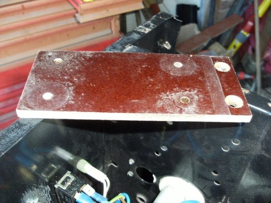
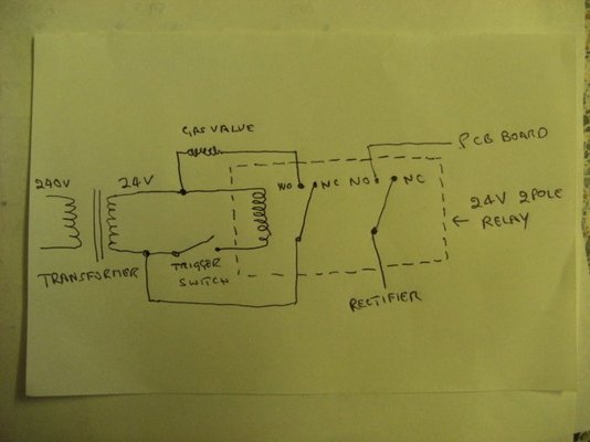
Hi Mike I get to weld another day ( Fried ). The brown stuff which is on top of the welder which I have always know as componsite ( though there is more than likely a proper name for it ) is the stuff I am go use for the euro connector insulation. Pondy has posted a firm that I will check out for the gas valve and wiring. The wiring diagram is how I thought of wiring up the gas valve and the power to the PCB board from the trigger switch. The old system basically used to run feed from the rectifier to to the trigger switch and when the switch was pressed the power then went to the PCB board. I already have the 240v AC relay with 24v AC coil.
Hi Mike I get to weld another day ( Fried ). The brown stuff which is on top of the welder which I have always know as componsite ( though there is more than likely a proper name for it ) is the stuff I am go use for the euro connector insulation. Pondy has posted a firm that I will check out for the gas valve and wiring. The wiring diagram is how I thought of wiring up the gas valve and the power to the PCB board from the trigger switch. The old system basically used to run feed from the rectifier to to the trigger switch and when the switch was pressed the power then went to the PCB board. I already have the 240v AC relay with 24v AC coil.