mike 109444
Member
- Messages
- 4,878
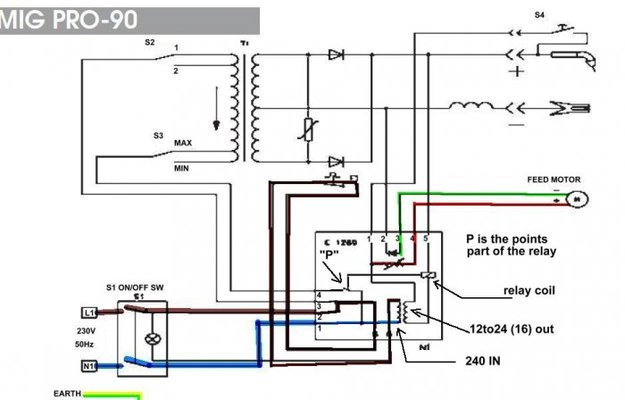
The diagram is like most, not the best! They don't show a lot of the components on the pcb. The Wirefeed motor takes it's control from the pcb. The way it is drawn is a little strange but as there is a transistor on the pcb (not shown in diagram!) it will need lower voltage to work hence why i say there is a lot not shown on diagram.
As Snooper has said it is possible to fit a transformer separately from the board and then take two wires from the pcb out to the transformer (the 240v spots on pcb) then the lower voltage generated by the transformer is sent back to pcb via two more wires and connected to where the original transformers output went. Bit like this that was being done on a SIP
http://www.mig-welding.co.uk/forum/showthread.php?t=40097
Have added bit more detail to diagram see pic