Hi All,
This is my first post so just introducing myself. Located in the Wye Valley on the Gloucestershire and South Wales border and a keen Land Rover fan (Series, Range Rover Classics, Disco 1 & 2). I did run a car repair business from my workshop but now only concentrate on my own projects, or try to, having just completed a full resto on a Series 2a 88 for a local chap.
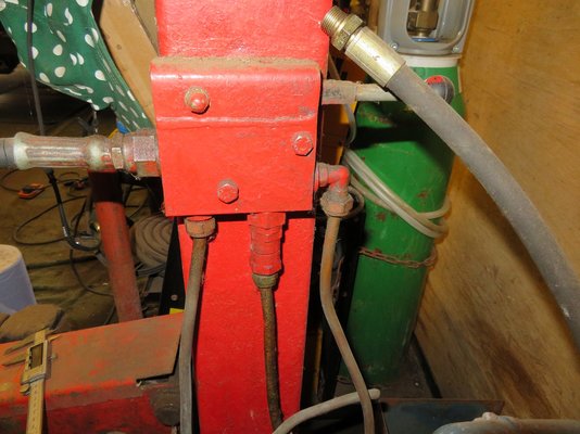
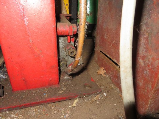
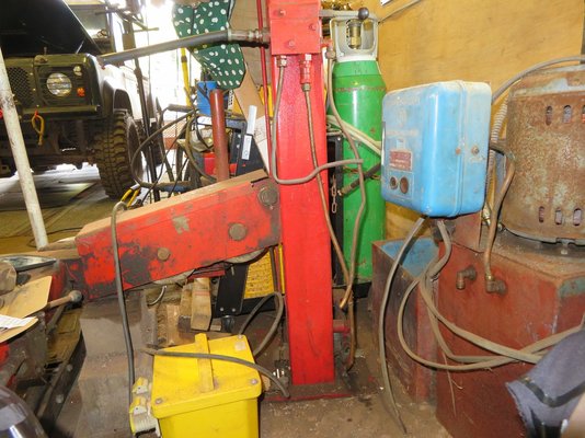
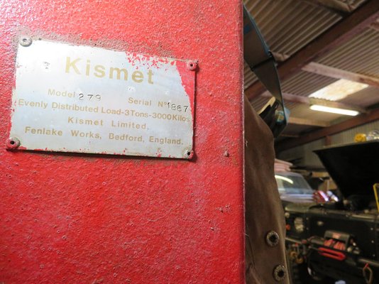
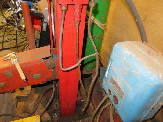
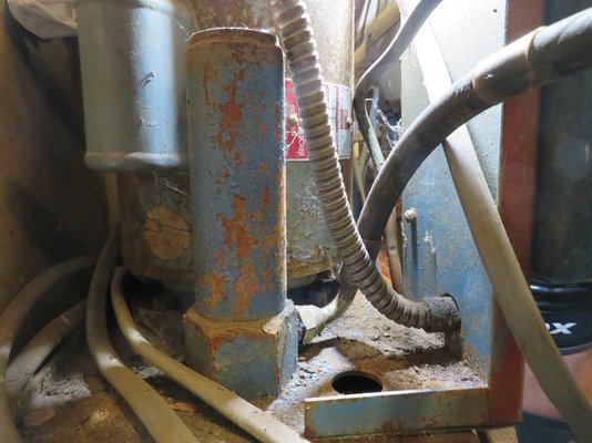
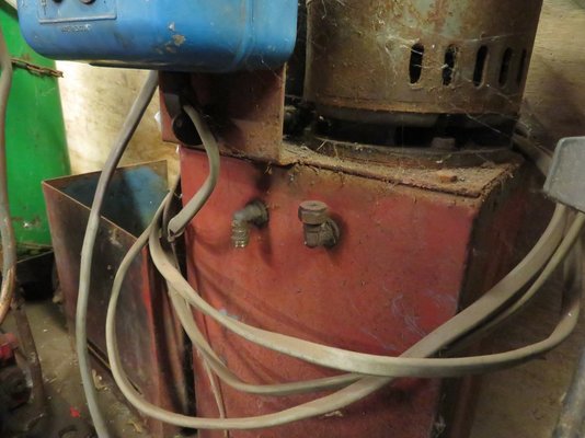
Anyway, on to the issue. A good while ago I bought this Kismet 279 ramp of a guy that was closing down but although I have seen the ramp in action when I came to pick it up most of the copper pipework was cut, bend or missing. I wish I had taken some photos when it was working and fully plumbed.
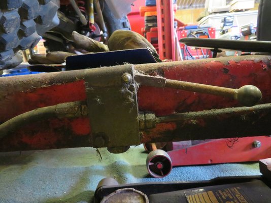
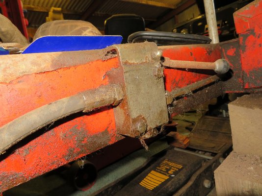
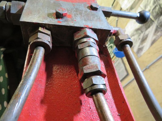
I'm now trying to recommission it and not entirely sure what goes where although on the main control block although there is existing pipework to the foot valve and I know the flexible that goes to the beam lifting valve on the ramp. I've searched for a hydraulic circuit diagram for this but know luck.
I was playing with the idea of using flexibles on all the connections but not sure if I should just replace it with copper. The fitting size is 3/8" bsp and the copper pipe is 3/8"o/d (10mm) thick wall - 7mm i/d.
From the pictures I'm hoping someone can help. I'm in the process of drawing up a circuit of how I think it goes but I think there maybe a couple of directions it could go.
Once I have completed the 2 versions I'll post them up for comments but if anyone has the knowledge then please help.
Many thanks in advance
blz6662


