Maker
Most folk just call me; Orange Joe
- Messages
- 10,645
- Location
- Keeler crater
I'm posting this partially to ask for help, partially because I think it might be interesting to some, and partially because I find it quite helpful to write down my thoughts as I work though something like this.
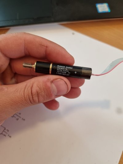
I've got a handful of these cute little motors, they've got a geared output and a 6 pin connector, so presumably there's an encoder in there. They're probably frighteningly expensive new, but without knowing what they are they're not much use to me. The product code, 344515, brings up nothing on the Maxon website, I emailed them and it's a customer specific part and they can't give any details without the OEM's express permission. I'd email the OEM but I've got no idea who they are, I've just got a bag of loose motors.
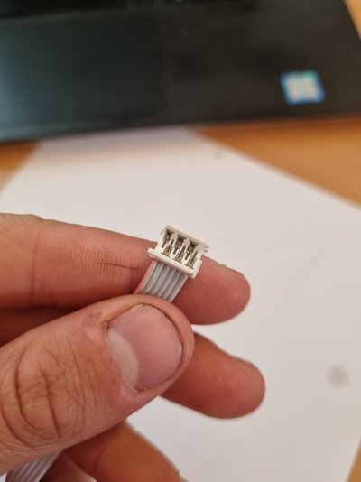
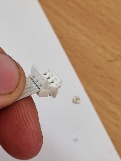
Here's the connector, I've seen them before but no idea what it's called, I'll buy a few if anyone recognises it?
Poking it with a multimeter, the two outermost wires have about 30 ohms between them and open circuit to the other four, spinning the shaft by hand I can get as much as 10VDC out on these pins, clearly it's a brushed DC motor, these are power leads, and I think 12V supply is a safe bet. The other four wires have 10k, 20k and 1 meg between them and nothing changes turning the shaft. It's gonna need a sacrifice one to the tare down gods.
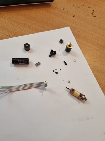
The back end came off with a bit of brute force and ignorance, there's tiny copper brushes on the other side of this piece which I forgot to take a picture of.
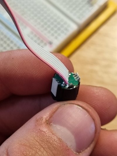
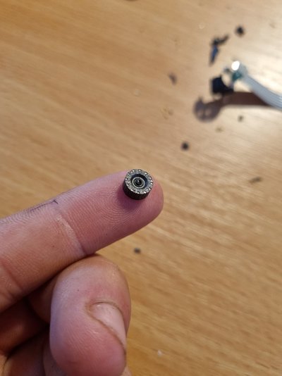
I chewed the black plastic off this to reveal a ferrite magnet encoder wheel. I can't tell how many poles it has, I think those 12 dots on it are just a feature on the die, I can't find my magnetic viewing film so I'm not sure if there's just two poles or something more clever going on.
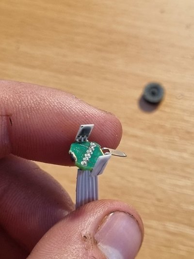
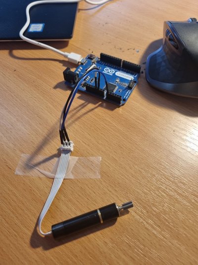
The wheel sat between these two white things, which I assume are hall effect sensors. They each have 3 terminals, if you label the wires on the ribbon cable 1 to 6, the rightmost terminal on both these parts is connected to 2, the centres are both connected to 5 and the left hand pins get their own wires, 3 and 4. That looks like 2 and 5 are power and ground, 3 and 4 are signal. I was hoping to test it with a magnet but I seem to have broken this board so I hooked up another motor to an arduino running the Analogue Read example code, because I don't have an oscilloscope. I connected pin 2 to 5V, pin 5 to GND and pin 3 to an analogue input, just guessed the voltage and polarity. Here's a screenshot from the serial monitor while slowly turning the shaft:

Perfect! It alternates between logical high and low while turning, looks like a nice sharp square wave too, very pleased with that. Clearly I guessed the polarity right first try, I tried it the other way round and the output just sits at a little under the supply voltage.
Hooking both sensors up, and struggling to use the serial plotter in the Arduino IDE, you can see there is a phase difference, whether it's 90 degrees or not I've got no idea, it's clearly not 180 though which is what I thought when I saw the diametrically opposed sensors.

I really need an oscilloscope!
That's just turning the shaft by hand, I'm sure it would be easier to see what's going on if I just powered the motor up, but I don't have a power supply indoors and I'm very wary of running it off the Arduino, I killed this laptop a when it was new and still under warranty (Thank god!) ago testing motors on an Arduino.

I've got a handful of these cute little motors, they've got a geared output and a 6 pin connector, so presumably there's an encoder in there. They're probably frighteningly expensive new, but without knowing what they are they're not much use to me. The product code, 344515, brings up nothing on the Maxon website, I emailed them and it's a customer specific part and they can't give any details without the OEM's express permission. I'd email the OEM but I've got no idea who they are, I've just got a bag of loose motors.
Here's the connector, I've seen them before but no idea what it's called, I'll buy a few if anyone recognises it?


Poking it with a multimeter, the two outermost wires have about 30 ohms between them and open circuit to the other four, spinning the shaft by hand I can get as much as 10VDC out on these pins, clearly it's a brushed DC motor, these are power leads, and I think 12V supply is a safe bet. The other four wires have 10k, 20k and 1 meg between them and nothing changes turning the shaft. It's gonna need a sacrifice one to the tare down gods.


The back end came off with a bit of brute force and ignorance, there's tiny copper brushes on the other side of this piece which I forgot to take a picture of.

I chewed the black plastic off this to reveal a ferrite magnet encoder wheel. I can't tell how many poles it has, I think those 12 dots on it are just a feature on the die, I can't find my magnetic viewing film so I'm not sure if there's just two poles or something more clever going on.


The wheel sat between these two white things, which I assume are hall effect sensors. They each have 3 terminals, if you label the wires on the ribbon cable 1 to 6, the rightmost terminal on both these parts is connected to 2, the centres are both connected to 5 and the left hand pins get their own wires, 3 and 4. That looks like 2 and 5 are power and ground, 3 and 4 are signal. I was hoping to test it with a magnet but I seem to have broken this board so I hooked up another motor to an arduino running the Analogue Read example code, because I don't have an oscilloscope. I connected pin 2 to 5V, pin 5 to GND and pin 3 to an analogue input, just guessed the voltage and polarity. Here's a screenshot from the serial monitor while slowly turning the shaft:

Perfect! It alternates between logical high and low while turning, looks like a nice sharp square wave too, very pleased with that. Clearly I guessed the polarity right first try, I tried it the other way round and the output just sits at a little under the supply voltage.
Hooking both sensors up, and struggling to use the serial plotter in the Arduino IDE, you can see there is a phase difference, whether it's 90 degrees or not I've got no idea, it's clearly not 180 though which is what I thought when I saw the diametrically opposed sensors.
I really need an oscilloscope!
That's just turning the shaft by hand, I'm sure it would be easier to see what's going on if I just powered the motor up, but I don't have a power supply indoors and I'm very wary of running it off the Arduino, I killed this laptop a when it was new and still under warranty (Thank god!) ago testing motors on an Arduino.


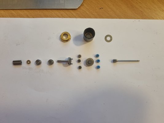


 Some kind of tiny motion control like that is interesting, I wonder how small a 3D printer could feasibly be.


