rtcosic
Forum Supporter
- Messages
- 2,871
- Location
- Warwickshire
Rewiring the indicator circuit.
1951 car, so 1955 C&U Regulations Part II B don't apply.
I have already modified the Lucas 'torpedo' side lights to twin filament and LED bulbs. The indicator source is very bright amber and the side light is white. The bulb includes a circuit that turns off the side light when the indicator is in service.
Currently, there are separate (ugly) rear indicators.
I have fitted LEDs to the side and brake lights. The side lights are very red and about as bright as the original brake lights. The brake light is also very red and very bright.
I want to use the brake lights as indicators, as was standard in the UK pre 1955 and seems to still be used in the USA.
I want to retain the Trafficators (Semaphores) and I have LED bulbs with integrated flasher units, so I do not need two separate power sources. I know this means these may not flash in unison with the other lamps.
I want to add a hazard switch.
I am in the process of assembling a board to carry all the new components and some others. This will sit under the dashboard out of sight.
I am copying this arrangement from YouTube.
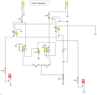
This is my proposed circuit:

This is the original vehicle wiring diagram with the colour code:

Can anyone spot any flaws before I make a start?
Can anyone recommend a suitable free drawing application that I can use to make a better diagram to retain for future reference? SketchUp seems rather clunky for this sort of thing. One with a shallow learning curve!
I am aware of the reproduction Lucas DB10 Flasher Lamp Relay, but using four relays is less than half the cost and easier for the mish-mash I'm planning and fully compatible with LEDs and anything else I might throw at it in the future.
I have switched the car to negative earth.
1951 car, so 1955 C&U Regulations Part II B don't apply.
I have already modified the Lucas 'torpedo' side lights to twin filament and LED bulbs. The indicator source is very bright amber and the side light is white. The bulb includes a circuit that turns off the side light when the indicator is in service.
Currently, there are separate (ugly) rear indicators.
I have fitted LEDs to the side and brake lights. The side lights are very red and about as bright as the original brake lights. The brake light is also very red and very bright.
I want to use the brake lights as indicators, as was standard in the UK pre 1955 and seems to still be used in the USA.
I want to retain the Trafficators (Semaphores) and I have LED bulbs with integrated flasher units, so I do not need two separate power sources. I know this means these may not flash in unison with the other lamps.
I want to add a hazard switch.
I am in the process of assembling a board to carry all the new components and some others. This will sit under the dashboard out of sight.
I am copying this arrangement from YouTube.
This is my proposed circuit:
This is the original vehicle wiring diagram with the colour code:
Can anyone spot any flaws before I make a start?
Can anyone recommend a suitable free drawing application that I can use to make a better diagram to retain for future reference? SketchUp seems rather clunky for this sort of thing. One with a shallow learning curve!
I am aware of the reproduction Lucas DB10 Flasher Lamp Relay, but using four relays is less than half the cost and easier for the mish-mash I'm planning and fully compatible with LEDs and anything else I might throw at it in the future.
I have switched the car to negative earth.


