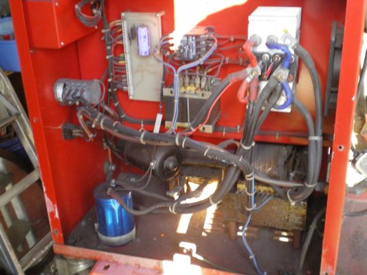
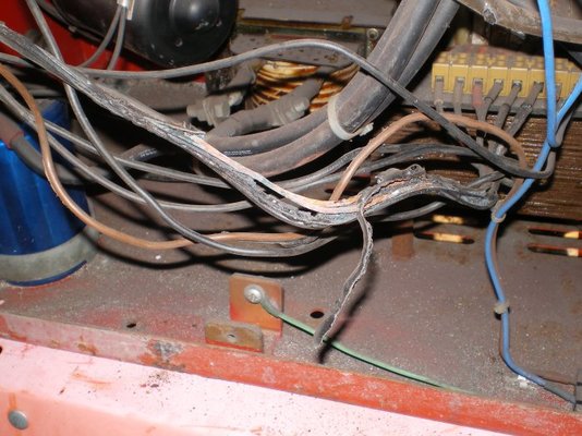
Seem to be spending a lot of time here just recently! Picked up a Britweld 195 mig today which was described as having 'not much control at low settings'. Got it home and removed side panel and found a few wires have been getting warmish. Ripped out the burnt ones and replaced with the intention of then firing up the machine to see if anything promising happened. When I tried setting at the lowest power on the rotary switch it seemed to be siezed and just the 'knob' was turning. Reluctantly I decided to take it apart and see if it could be salvaged. Knowing full well how many springs and little bits can fly out of this type of unit I was suitably gentle and quite chuffed when all came apart and nothing shot across the room. Unfortunately I didn't realise that each switch unit (7 of them activated by a lobe running on a cam) could be placed either way up. In other words each of the switches had two possible positions. Maths isn't my strong point but the odds of getting seven switches in the right orientation by luck isn't good. There aren't any marks or indicators of where they were placed so I tried a logical approach and placed each in order one up, one down. I don't think I got it right and am not happy about connecting it up and causing more mayhem!
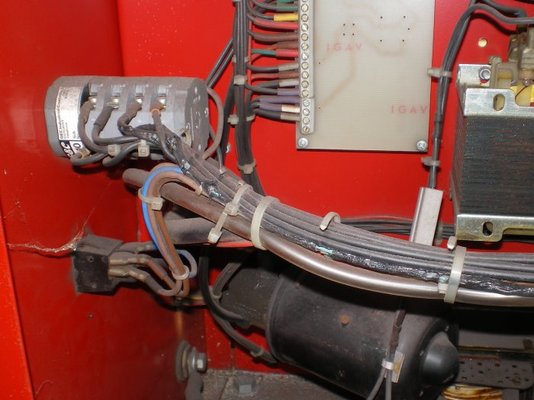
The unit appears to have power from the contactor applied to one side of each switch (they are all jumpered together). This leaves seven connections and seven wires. The seven wires all come from the 'chocolate block' connector as you can see in the photo's. Would anyone know if these seven connections are simply a line of tappings which should be connected in sequence via the selector switch or is it more likely they are connected in some more complicated way to select different combinations of primary windings rather than just a step ladder type of sequence.
Hope I've explained all this well enough for somebody to make sense of? I would guess the chances of finding a wiring diagram for this machine is slimmish- unless you know better???? Any advice appreciated.
Thanks
John