You are using an out of date browser. It may not display this or other websites correctly.
You should upgrade or use an alternative browser.
You should upgrade or use an alternative browser.
205te no wire feed
- Thread starter Hutcho
- Start date
mike 109444
Member
- Messages
- 4,671
Bit stuck for time at the moment but if you download the manual in this link you will see that the machine is built at same time as the 195 and 230 so do a forum search for same issue on those models should get you started https://www.mig-welding.co.uk/forum/threads/clark-230.76828/
ps there is a fuse on the pcb !
ps there is a fuse on the pcb !
Thanks mike - I’ve checked the fuse - when trigger is pressed Iam only getting 0.2 of a volt going to motor - I’ve changed the three trannys and still no joy - I did notice after I posted that they is a 27k resistor snapped off so waiting for some to come - relay near pcb transformer is working - but thanks for the reply much appreciated
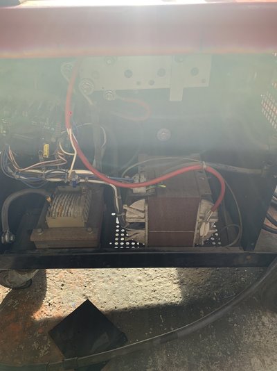
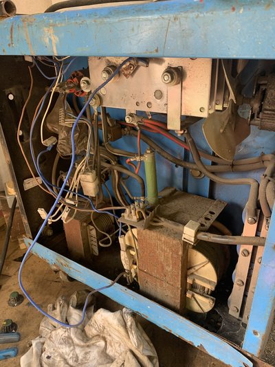
Looking at the picture above of the inside of the machine, I can't find the auxiliary transformer, which would provide 24v. There isn't one!
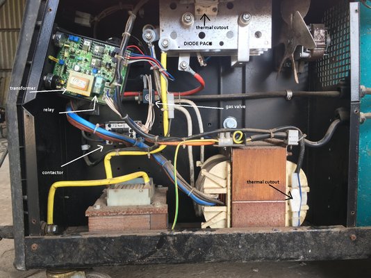
The transformer on the PCB is so small, it can only run the relay on the PCB. That means the small relay switches AC mains to the Contactor ( and the gas valve ). This could be confirmed by checking if the operating voltage is marked on the coils of those two components.
When the small relay closes, which does happen, it is supposed to send mains to the Contactor, which powers up the main welding transformer, and the welding current output is tapped off via the speed controller to run the wirefeed. Something is getting lost in that sequence.
Is there a manual operating button on the top of the Contactor? If so, pressing it may make the machine burst into life.
If the Contactor pulls in on pressing the trigger, I guess the machine actually does arc at the wire tip, and the gas valve opens?
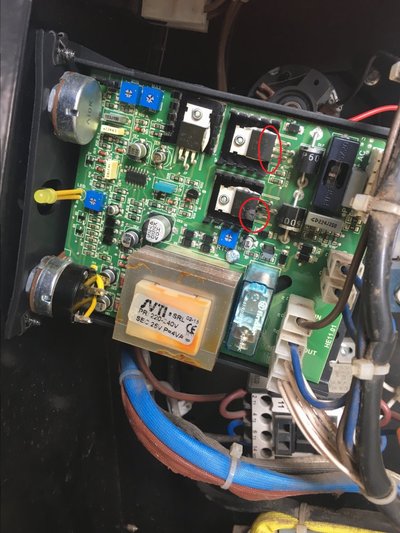
If so, I didn't understand that it is really only the wirefeed that does not work. From the diagram that Mike 109444 linked to, the power circuits on the PCB are fed from the main welding transformer, but initially with AC. This comes in on the two thin blue wires, pins 1 & 2 of the multi-pin connector. Depending on the power range selected, you should see around 20v AC on those two wires. As Mike said, there is a 5 Amp fuse under that black platic lid.
I think the power semiconductors are thyristors ( SCRs ), and two of them, together with the two fat diodes, form a controlled bridge rectifier.
This thread describes the board:
https://www.mig-welding.co.uk/forum/threads/clarke-250t-blowing-pcb-fuse.99377/#post-1520493
If the Contactor pulls in on pressing the trigger, I guess the machine actually does arc at the wire tip, and the gas valve opens?
If so, I didn't understand that it is really only the wirefeed that does not work. From the diagram that Mike 109444 linked to, the power circuits on the PCB are fed from the main welding transformer, but initially with AC. This comes in on the two thin blue wires, pins 1 & 2 of the multi-pin connector. Depending on the power range selected, you should see around 20v AC on those two wires. As Mike said, there is a 5 Amp fuse under that black platic lid.
I think the power semiconductors are thyristors ( SCRs ), and two of them, together with the two fat diodes, form a controlled bridge rectifier.
This thread describes the board:
https://www.mig-welding.co.uk/forum/threads/clarke-250t-blowing-pcb-fuse.99377/#post-1520493
The speed control on this PCB is a bit unusual. Rather than a simple linear variable current source, or a clever Pulse-Width Modulated ( PWM ) controller, it uses AC from the welding transformer and feeds it to the motor through a controlled bridge rectifier, using two diodes and two SCRs. It also has an extra SCR that shorts the motor to act as a brake. Whoever designed this was showing off a bit.
( As per the thread I linked above, if the Brake SCR goes on by mistake, it can blow the 5 Amp fuse on the PCB.)
We do not have a circuit diagram, and I think the problem is in the trigger pulse timing section, so it won't be an easy fix. The fact that the trigger switches the small relay on, and that the 20v AC feed is present on the two thin blue wires means that the fault is definitely in the PCB itself. For £83 you could send the board to TecArc for repair:
https://www.ebay.co.uk/itm/CLARKE-O...ELDER-CONTROL-PCB-REPAIR-SERVICE/113711433794
However, if you decide to continue with the troubleshooting exercise:
There are two SCRs in the speed controller. If one was short-circuit, the motor would run constantly at half speed. If one was open-circuit, the wirefeed motor would still work, but only up to half-speed. Neither of these two conditions apply, the motor does not run at all, and since it is unlikely that more than one component failed initially, I suspect that both SCRs are OK but they are not receiving trigger pulses. To check for this, you would need access to an oscilloscope to check for the trigger pulses on the gates of the SCRs.
According to the picture of the PCB on the TecArc eBay link above, the SCRs are type BT151 :

An SCR is like a diode, in that it will conduct in one direction only - from Anode to Cathode. However, that will only happen when the SCR is triggered, by applying a small voltage or pulse ( 3v DC ) to the Gate. The trigger voltage needs to be positive on the gate, negative on the cathode.
To be certain, you could test the SCRs by taking them off the PCB and rigging up a test circuit with a 12v battery, the positive wired through a 21 Watt car bulb to the anode, and the cathode to the negative of the battery. The bulb should not light until you briefly apply +3v ( e.g. two AA cells in series ) to the gate, with the negative of that 3v to the cathode. The SCR will then conduct and the bulb will light up. It will stay on even after you remove the trigger pulse. Once an SCR starts conducting, it will remain on until the current flow is removed or reversed.
If you have two spare medium or high current diodes, similar to or larger than the two fat ones already mounted on the PCB, you could temporarily fit them to the PCB in place of the two speed control thyristors. Link them with wires the same as the SCRs should be, anode to the anode track, cathode to the cathode track. Since they are only diodes, there will be no Gate connection, and they will conduct full-time as diodes. We now have a 4-diode bridge rectifier, not an SCR Controlled Bridge Rectifier. The result will be that the motor should run at full speed, regardless of the speed control setting. This test proves that we are just missing the SCR trigger pulses.
With the SCRs soldered back where they should be on the PCB, we need to look for positive pulses, about 3v, on the gates of both SCRs. To see this, you'll need an oscilloscope. The ground of the scope probe should go to the SCR cathode. These pulses will be at 100Hz, and synchonised to the AC mains. The pulses should be there after pressing the torch trigger, and the pulse width will vary, depending on the setting of the speed control knob. I'm guessing that the pulses will not be there at the SCR gates. Then comes the hard bit, following the PCB track backwards towards the pulse timing circuit, identifying the components and reverse-engineering a circuit diagram until the faulty component is located.
( As per the thread I linked above, if the Brake SCR goes on by mistake, it can blow the 5 Amp fuse on the PCB.)
We do not have a circuit diagram, and I think the problem is in the trigger pulse timing section, so it won't be an easy fix. The fact that the trigger switches the small relay on, and that the 20v AC feed is present on the two thin blue wires means that the fault is definitely in the PCB itself. For £83 you could send the board to TecArc for repair:
https://www.ebay.co.uk/itm/CLARKE-O...ELDER-CONTROL-PCB-REPAIR-SERVICE/113711433794
However, if you decide to continue with the troubleshooting exercise:
There are two SCRs in the speed controller. If one was short-circuit, the motor would run constantly at half speed. If one was open-circuit, the wirefeed motor would still work, but only up to half-speed. Neither of these two conditions apply, the motor does not run at all, and since it is unlikely that more than one component failed initially, I suspect that both SCRs are OK but they are not receiving trigger pulses. To check for this, you would need access to an oscilloscope to check for the trigger pulses on the gates of the SCRs.
According to the picture of the PCB on the TecArc eBay link above, the SCRs are type BT151 :
An SCR is like a diode, in that it will conduct in one direction only - from Anode to Cathode. However, that will only happen when the SCR is triggered, by applying a small voltage or pulse ( 3v DC ) to the Gate. The trigger voltage needs to be positive on the gate, negative on the cathode.
To be certain, you could test the SCRs by taking them off the PCB and rigging up a test circuit with a 12v battery, the positive wired through a 21 Watt car bulb to the anode, and the cathode to the negative of the battery. The bulb should not light until you briefly apply +3v ( e.g. two AA cells in series ) to the gate, with the negative of that 3v to the cathode. The SCR will then conduct and the bulb will light up. It will stay on even after you remove the trigger pulse. Once an SCR starts conducting, it will remain on until the current flow is removed or reversed.
If you have two spare medium or high current diodes, similar to or larger than the two fat ones already mounted on the PCB, you could temporarily fit them to the PCB in place of the two speed control thyristors. Link them with wires the same as the SCRs should be, anode to the anode track, cathode to the cathode track. Since they are only diodes, there will be no Gate connection, and they will conduct full-time as diodes. We now have a 4-diode bridge rectifier, not an SCR Controlled Bridge Rectifier. The result will be that the motor should run at full speed, regardless of the speed control setting. This test proves that we are just missing the SCR trigger pulses.
With the SCRs soldered back where they should be on the PCB, we need to look for positive pulses, about 3v, on the gates of both SCRs. To see this, you'll need an oscilloscope. The ground of the scope probe should go to the SCR cathode. These pulses will be at 100Hz, and synchonised to the AC mains. The pulses should be there after pressing the torch trigger, and the pulse width will vary, depending on the setting of the speed control knob. I'm guessing that the pulses will not be there at the SCR gates. Then comes the hard bit, following the PCB track backwards towards the pulse timing circuit, identifying the components and reverse-engineering a circuit diagram until the faulty component is located.
The speed control on this PCB is a bit unusual. Rather than a simple linear variable current source, or a clever Pulse-Width Modulated ( PWM ) controller, it uses AC from the welding transformer and feeds it to the motor through a controlled bridge rectifier, using two diodes and two SCRs. It also has an extra SCR that shorts the motor to act as a brake. Whoever designed this was showing off a bit.
( As per the thread I linked above, if the Brake SCR goes on by mistake, it can blow the 5 Amp fuse on the PCB.)
We do not have a circuit diagram, and I think the problem is in the trigger pulse timing section, so it won't be an easy fix. The fact that the trigger switches the small relay on, and that the 20v AC feed is present on the two thin blue wires means that the fault is definitely in the PCB itself. For £83 you could send the board to TecArc for repair:
https://www.ebay.co.uk/itm/CLARKE-O...ELDER-CONTROL-PCB-REPAIR-SERVICE/113711433794
However, if you decide to continue with the troubleshooting exercise:
There are two SCRs in the speed controller. If one was short-circuit, the motor would run constantly at half speed. If one was open-circuit, the wirefeed motor would still work, but only up to half-speed. Neither of these two conditions apply, the motor does not run at all, and since it is unlikely that more than one component failed initially, I suspect that both SCRs are OK but they are not receiving trigger pulses. To check for this, you would need access to an oscilloscope to check for the trigger pulses on the gates of the SCRs.
According to the picture of the PCB on the TecArc eBay link above, the SCRs are type BT151 :
View attachment 236169
An SCR is like a diode, in that it will conduct in one direction only - from Anode to Cathode. However, that will only happen when the SCR is triggered, by applying a small voltage or pulse ( 3v DC ) to the Gate. The trigger voltage needs to be positive on the gate, negative on the cathode.
To be certain, you could test the SCRs by taking them off the PCB and rigging up a test circuit with a 12v battery, the positive wired through a 21 Watt car bulb to the anode, and the cathode to the negative of the battery. The bulb should not light until you briefly apply +3v ( e.g. two AA cells in series ) to the gate, with the negative of that 3v to the cathode. The SCR will then conduct and the bulb will light up. It will stay on even after you remove the trigger pulse. Once an SCR starts conducting, it will remain on until the current flow is removed or reversed.
If you have two spare medium or high current diodes, similar to or larger than the two fat ones already mounted on the PCB, you could temporarily fit them to the PCB in place of the two speed control thyristors. Link them with wires the same as the SCRs should be, anode to the anode track, cathode to the cathode track. Since they are only diodes, there will be no Gate connection, and they will conduct full-time as diodes. We now have a 4-diode bridge rectifier, not an SCR Controlled Bridge Rectifier. The result will be that the motor should run at full speed, regardless of the speed control setting. This test proves that we are just missing the SCR trigger pulses.
With the SCRs soldered back where they should be on the PCB, we need to look for positive pulses, about 3v, on the gates of both SCRs. To see this, you'll need an oscilloscope. The ground of the scope probe should go to the SCR cathode. These pulses will be at 100Hz, and synchonised to the AC mains. The pulses should be there after pressing the torch trigger, and the pulse width will vary, depending on the setting of the speed control knob. I'm guessing that the pulses will not be there at the SCR gates. Then comes the hard bit, following the PCB track backwards towards the pulse timing circuit, identifying the components and reverse-engineering a circuit diagram until the faulty component is located.
Thankyou - will give it a go tomorrowThe speed control on this PCB is a bit unusual. Rather than a simple linear variable current source, or a clever Pulse-Width Modulated ( PWM ) controller, it uses AC from the welding transformer and feeds it to the motor through a controlled bridge rectifier, using two diodes and two SCRs. It also has an extra SCR that shorts the motor to act as a brake. Whoever designed this was showing off a bit.
( As per the thread I linked above, if the Brake SCR goes on by mistake, it can blow the 5 Amp fuse on the PCB.)
We do not have a circuit diagram, and I think the problem is in the trigger pulse timing section, so it won't be an easy fix. The fact that the trigger switches the small relay on, and that the 20v AC feed is present on the two thin blue wires means that the fault is definitely in the PCB itself. For £83 you could send the board to TecArc for repair:
https://www.ebay.co.uk/itm/CLARKE-O...ELDER-CONTROL-PCB-REPAIR-SERVICE/113711433794
However, if you decide to continue with the troubleshooting exercise:
There are two SCRs in the speed controller. If one was short-circuit, the motor would run constantly at half speed. If one was open-circuit, the wirefeed motor would still work, but only up to half-speed. Neither of these two conditions apply, the motor does not run at all, and since it is unlikely that more than one component failed initially, I suspect that both SCRs are OK but they are not receiving trigger pulses. To check for this, you would need access to an oscilloscope to check for the trigger pulses on the gates of the SCRs.
According to the picture of the PCB on the TecArc eBay link above, the SCRs are type BT151 :
View attachment 236169
An SCR is like a diode, in that it will conduct in one direction only - from Anode to Cathode. However, that will only happen when the SCR is triggered, by applying a small voltage or pulse ( 3v DC ) to the Gate. The trigger voltage needs to be positive on the gate, negative on the cathode.
To be certain, you could test the SCRs by taking them off the PCB and rigging up a test circuit with a 12v battery, the positive wired through a 21 Watt car bulb to the anode, and the cathode to the negative of the battery. The bulb should not light until you briefly apply +3v ( e.g. two AA cells in series ) to the gate, with the negative of that 3v to the cathode. The SCR will then conduct and the bulb will light up. It will stay on even after you remove the trigger pulse. Once an SCR starts conducting, it will remain on until the current flow is removed or reversed.
If you have two spare medium or high current diodes, similar to or larger than the two fat ones already mounted on the PCB, you could temporarily fit them to the PCB in place of the two speed control thyristors. Link them with wires the same as the SCRs should be, anode to the anode track, cathode to the cathode track. Since they are only diodes, there will be no Gate connection, and they will conduct full-time as diodes. We now have a 4-diode bridge rectifier, not an SCR Controlled Bridge Rectifier. The result will be that the motor should run at full speed, regardless of the speed control setting. This test proves that we are just missing the SCR trigger pulses.
With the SCRs soldered back where they should be on the PCB, we need to look for positive pulses, about 3v, on the gates of both SCRs. To see this, you'll need an oscilloscope. The ground of the scope probe should go to the SCR cathode. These pulses will be at 100Hz, and synchonised to the AC mains. The pulses should be there after pressing the torch trigger, and the pulse width will vary, depending on the setting of the speed control knob. I'm guessing that the pulses will not be there at the SCR gates. Then comes the hard bit, following the PCB track backwards towards the pulse timing circuit, identifying the components and reverse-engineering a circuit diagram until the faulty component is located.
Well after a few weeks off not touching it and others to repair - I got a Clarke 185 in cheap - so out of curiosity I thought I wonder if that board would fit the 205 - and yes it does - need to sort one wire out but she works again