


You are using an out of date browser. It may not display this or other websites correctly.
You should upgrade or use an alternative browser.
You should upgrade or use an alternative browser.
Sealey 150/5 euro torch gas solenoid valve wiring
- Thread starter ryan darrington
- Start date
ryan darrington
New Member
- Messages
- 17
- Location
- Newcastle
Do u know which wire that is on my machine.!!! From my pictures?
the snooper
getting older by the day
- Messages
- 21,063
- Location
- Hull UK
look on the circuit board fs1
the snooper
getting older by the day
- Messages
- 21,063
- Location
- Hull UK
it is an R and shows the gas solenoid connected to it, which I suspect is the heat resistant insulated wire shown from the pcbThe one marked B (That R may be a B on the diagram?) All the other wires have heat-resistant insulation on them and go to the transformer.
ryan darrington
New Member
- Messages
- 17
- Location
- Newcastle
This is the circuit board with those connects removed no labels?look on the circuit board fs1
ryan darrington
New Member
- Messages
- 17
- Location
- Newcastle
The one on my welder marked B (on the power switch) has the neutral wire from the 3 pin plug and my blue wire from the solenoid connected to it.!The one marked B (That R may be a B on the diagram?) All the other wires have heat-resistant insulation on them and go to the transformer.
rtbcomp
Moderator
- Messages
- 18,575
- Location
- Sheffield UK
Looking again - that diagram doesn't correspond exactly with the switch.
There's a red wire going to the switch, this maybe this is the R terminal. Can you get a dental mirror and have a look what the markings are on the bottom of the switch?
There's a red wire going to the switch, this maybe this is the R terminal. Can you get a dental mirror and have a look what the markings are on the bottom of the switch?
the snooper
getting older by the day
- Messages
- 21,063
- Location
- Hull UK
its the inner most terminal the outer should be live all the time when powered up
the snooper
getting older by the day
- Messages
- 21,063
- Location
- Hull UK
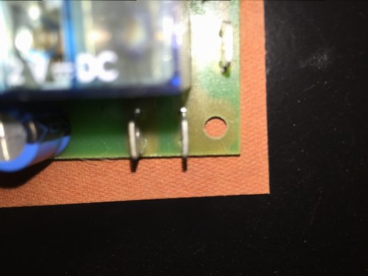
here is one of those boards clearly showing the circuit board track that also feed the aux transformer

rtbcomp
Moderator
- Messages
- 18,575
- Location
- Sheffield UK
The one on my welder marked B (on the power switch) has the neutral wire from the 3 pin plug and my blue wire from the solenoid connected to it.!
Is there an "OFF" position on that switch? If so that explains the live & neutral connected to it.
That's OK - try connecting the other solenoid wire to the one marked "R".
the snooper
getting older by the day
- Messages
- 21,063
- Location
- Hull UK
this should be simple, cant see why things are going wrong the board has connections as follows

ryan darrington
New Member
- Messages
- 17
- Location
- Newcastle
This has gotten really confusing.!!!
Too many fs1 B R and what nots floating around..
Stick the solenoid blue wire into...
Stick the solenoid brown wire into...
Too many fs1 B R and what nots floating around..
Stick the solenoid blue wire into...
Stick the solenoid brown wire into...
the snooper
getting older by the day
- Messages
- 21,063
- Location
- Hull UK
try connecting to the ones on the board marked switched live and connect the other solenoid wire to the other marked neutral in the pic above it should work
the snooper
getting older by the day
- Messages
- 21,063
- Location
- Hull UK
I wonder if the switch is in the neutral side of the transformer, so we should be looking to connect the other side of the valve to a live rather than a neutral?
you could well be right but if he just connects as in the picture above it will work
ryan darrington
New Member
- Messages
- 17
- Location
- Newcastle
try connecting to the ones on the board marked switched live and connect the other solenoid wire to the other marked neutral in the pic above it should work
And we have a WINNER....
Seems the issue was i had the neutral connected to the 3 pin plug neutral...
YOU GUYS ARE SPAMTASTIC
I am a member of many different forum but by far this has been the best for advice information guidance and speed.. Keep up the good work...
For my next question... What TIG welder should i buy for around £600
rtbcomp
Moderator
- Messages
- 18,575
- Location
- Sheffield UK
For my next question... What TIG welder should i buy for around £600
Pass - try the £600 Tig Welder Shop!
Glad you got it sorted, it's nice to know how people get on
the snooper
getting older by the day
- Messages
- 21,063
- Location
- Hull UK
And we have a WINNER....
View attachment 63223
Seems the issue was i had the neutral connected to the 3 pin plug neutral...
YOU GUYS ARE SPAMTASTIC
I am a member of many different forum but by far this has been the best for advice information guidance and speed.. Keep up the good work...
For my next question... What TIG welder should i buy for around £600
i'll get my coat
 never tried tig so cant help but there are many that can and will help, just start a new thread