Donsc
New Member
- Messages
- 13
- Location
- Canada, Okanagan


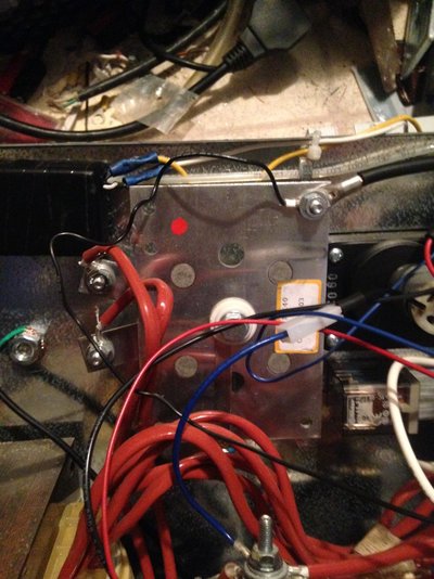
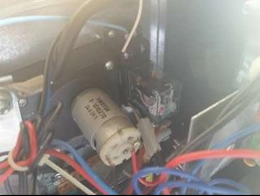
Thank you for your reply, But a little confused as to your meaning, Sorry. Here is the config I have inside. The two red wires come off the secondary on the main transformer and the black wire (large) from the rectifier goes to the Pos + out on the polarity. The black from the drive motor is connected to the neg off the secondary , if that makes sense to you? If I could have help identifying the ones I need to use I would greatly appreciate it.There should be an input (sometimes two, one of which may be connected to the output side of the choke) to the pcb from the main rectifier and an output to the motor (if there's two inputs from the rectified power there will be two outputs, if there's one then the other side of the motor should go to the negative of the rectified power line).
You need to identify these, and replace those inputs with your new psu outputs.
That should give you speed control using the existing front panel knob.
You will lose the "pseudo synergic" facility of having wire speed change automatically when you change the power settings, but the benefits of a stable feed hugely outweigh that 'loss'.
Thank YouHave a look at this thread, it might save me some typing
http://www.mig-welding.co.uk/forum/threads/sip-cosmo-mods.4061/
If you have any questions relating to that, reply here and I'll get notified and be happy to help further.
")


Well I'm just a hobby welder and certainly no pro, Just wanted to make this DC welder a little more capable and improve on the welds a bit. With the addition of the fan I installed and this controller, Might make a bit of a difference. Just bothers me that I'm not getting the curve in this mod lolTo be honest, that solution is probably as good as what's original for voltage control.
Having a more stable supply (instead of running off the weld transformer) is going to make it better too.
Seeing as you appear to know what you're doing () here's what I'd do...
Ditch the oem speed control, just use the switching portion of the pcb (or, even better convert to a 2 wire torch switch and put a decent contactor in).
Get/build a better pwm controller for the wire feed voltage control to get better low speed torque.
Add a brake resistor in the control relay circuit to stop feed run on - kind of like a very rudimentary burn back control.

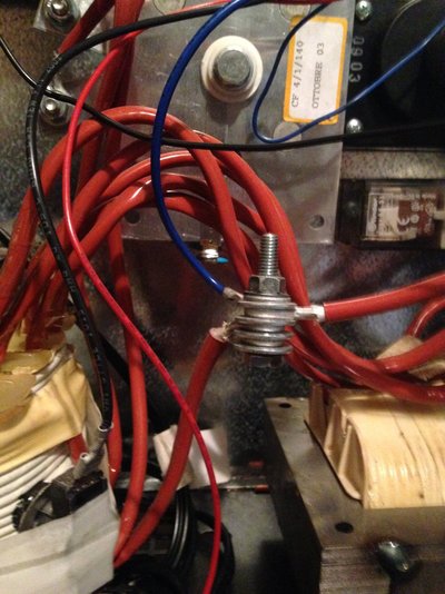
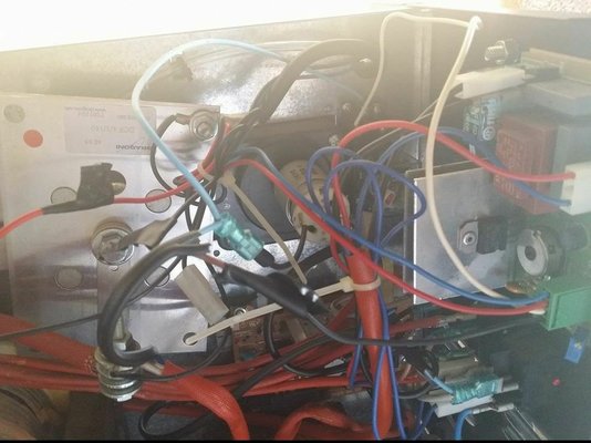
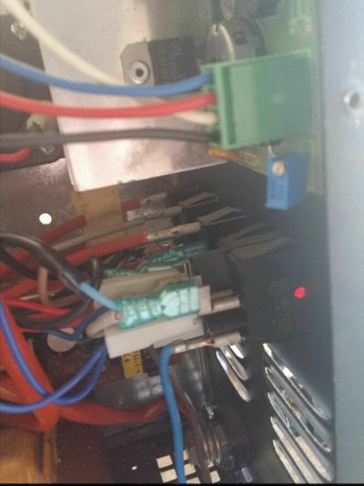
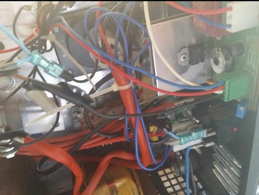
Thank you, The only wire from my rectifier to the pcb is the small black wire in picture attached and the large black one with it goes to + on the front of welder for gun. also the blue wire in other pic off of the large transformer goes to the neg side of the feed motor.For speed control, there will be a wire going from the positive (output) side of the recifier to the pcb - take that out and put your psu positive in it's place on the pcb.
There will be a wire from the negative lead (on the choke?) going to the motor - take that out and put your psu negative in it's place on the motor.
I can't say "cut the blue wire" because they use random colours on these machines, black on yours might be red or purple on mine - plus different market, you can't buy a 120volt sip 90 here because we simply don't use 120volt.
Thanks, So If I find the 120v that only engages when trigger is pulled that should do it then yes? sorry no lol The pos side of the feed motor runs to the trigger and motor doesn't run until trigger is pressed so if psu was hooked direct to 120v would that not be it? Sorry for all the questions....It'll be those then, for the 24v out from your psu.
You just need to deal with the power in to your psu so the wire doesn't feed all the time.
Yes, Found that out lol It's a switch mode psu as well so I guess I need to figure how to have the 24v dc side power on/off with trigger as its not healthy for the psu to be constantly switching sighhh so difficult lolStandard config:
Trigger controls relay. Relay controls big transformer. Big transformer melts metal AND drives wire feed through speed control.
So, if you hook your new psu direct to incoming mains, it'll run all the time power is on, whether you pull the trigger or not.
I do have a step down transformer (several actually) that could handle being switched on and off. 120v-24v ac and a bridge rectifier. Or would I still need a relay hooked up somewhere?You could run another 12v coil relay in parallel with the one on the pcb to switch the 24v between the psu and pcb...
It'd have to be a little coil though as the pcb transformer is teeny tiny, or you replace that as well with a slightly bigger one.
Or, if you put in a double throw relay between the pcb and motor you could switch in a brake resistor.
Well, I have another predicament. I can only seem to track down a mains source that switches with the trigger that is only putting out 60v. 1/2 of the stepdown transformers rated input. I can only get a bit over 12v out from transformer maybe 14 with the rectifier but I believe the motor runs at 24v total. I'm sooooo close, any thoughts?That'd probably do it, but be aware that'll give you around 33 volts dc out of the rectifier so you may need to adjust the trimpot a bit.
The only reason to run a secondary relay is to switch the low voltage side, if you're switching the mains then just use what's already doing that.