


You are using an out of date browser. It may not display this or other websites correctly.
You should upgrade or use an alternative browser.
You should upgrade or use an alternative browser.
BROKEN HELP!
- Thread starter Rbchristy
- Start date
mike 109444
Member
- Messages
- 4,666
There should be some fuses inside the machine, items 39 on pic. Also there is a circuit breaker on the rear, item 31 but would have thought that would remove all power to machine.
And welcome BTW

And welcome BTW
mike 109444
Member
- Messages
- 4,666
Not sure if you have checked the fuses yet. You did not mention the fault light was on.
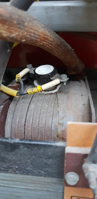
There are two thermal cutouts (TH1 & TH2) that if one (or both) is operated will light the FAULT light
One should be mounted to the diode pack/rectifier and the other mounted to the main transformer.

There are two thermal cutouts (TH1 & TH2) that if one (or both) is operated will light the FAULT light
One should be mounted to the diode pack/rectifier and the other mounted to the main transformer.
mike 109444
Member
- Messages
- 4,666
I assume the "checked" you have done refer to the fuses. If they are ok then the next item would be the thermal cut out(s).
THE BELOW IS DONE WITH THE MACHINE UNPLUGED FROM THE MAINS
What you need to be aware of when metering is that some items need to be fully or partly taken out of circuit to test.
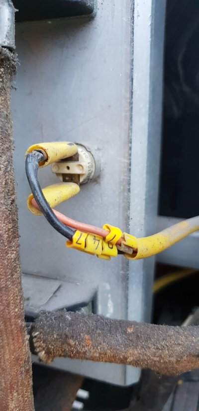
For the thermal cut outs it should be sufficient to pull one wire from the pair of cut outs to be able to test both.
If you pull say the pink wire from the cut out on diode pack you should now be able to meter both.
With your meter set to Ohms (the up side down horse shoe looking symbol !) and on it;s lowest range (not sure what type of meter you have).
Put one of the meter probes on the now free (where the pink wire was) terminal and the other on the terminal where the black wire connects to (or even into the back of it's spade connector). If the device is ok you should see on your meter a dead short. If the device is duff then you will see an open circuit.
To test the other cut out, LEAVE the pink wire off and now put your meter probes on each side of the cut out mounted on the transformer. Again if the device is ok you will see a dead short, if duff then you will see an open circuit.
A basic explanation of how the cut outs and the fault light works. In normal (non fault condition) power (27Vac) goes through TH1 and TH2 to the pcb but NOT through the FAULT light. If the machine is run hard (high power + long runs) then one of the thermal cut outs MAY operate (go open) The power (27Vac) now goes through the FAULT light which now lights! This STOPS the welder welding but will still allow SOME items on the machine to work such as the fan which should cool the machine and after a while..... the cut out should cut back in. Sometimes they can stick off.
Thermal devices like this are found on many items such as central heating boilers and electric showers
The pics below are of one of my meters showing 1) an open circuit reading (probes are not touching). 2) a dead short (probes touching) note you don't always see a perfect dead short as the probes may not make a perfect contact, hence the 00.6 reading).


THE BELOW IS DONE WITH THE MACHINE UNPLUGED FROM THE MAINS
What you need to be aware of when metering is that some items need to be fully or partly taken out of circuit to test.
For the thermal cut outs it should be sufficient to pull one wire from the pair of cut outs to be able to test both.
If you pull say the pink wire from the cut out on diode pack you should now be able to meter both.
With your meter set to Ohms (the up side down horse shoe looking symbol !) and on it;s lowest range (not sure what type of meter you have).
Put one of the meter probes on the now free (where the pink wire was) terminal and the other on the terminal where the black wire connects to (or even into the back of it's spade connector). If the device is ok you should see on your meter a dead short. If the device is duff then you will see an open circuit.
To test the other cut out, LEAVE the pink wire off and now put your meter probes on each side of the cut out mounted on the transformer. Again if the device is ok you will see a dead short, if duff then you will see an open circuit.
A basic explanation of how the cut outs and the fault light works. In normal (non fault condition) power (27Vac) goes through TH1 and TH2 to the pcb but NOT through the FAULT light. If the machine is run hard (high power + long runs) then one of the thermal cut outs MAY operate (go open) The power (27Vac) now goes through the FAULT light which now lights! This STOPS the welder welding but will still allow SOME items on the machine to work such as the fan which should cool the machine and after a while..... the cut out should cut back in. Sometimes they can stick off.
Thermal devices like this are found on many items such as central heating boilers and electric showers
The pics below are of one of my meters showing 1) an open circuit reading (probes are not touching). 2) a dead short (probes touching) note you don't always see a perfect dead short as the probes may not make a perfect contact, hence the 00.6 reading).
Thank you so much Mike for that in-depth description of what to check for I have done that and the readings are what they should be for both of the thermal cut-out switches that I pictured and I'm still getting nothing from the world are apart from the fan coming on and the wire speed although the fault light hasn't come on thanks
mike 109444
Member
- Messages
- 4,666
If you set your meter to AC volts and meter between a9 and a8, you should see 27 Vac (you don't need to pull trigger just have machine switched on)
To find a9 and a8 look at the pic below (this is a 245 pcb but has similar plug/socket, the one on the left!) You need the right hand side pins. If there is 27 volts then there is a fault/issue on your pcb or further on in the wiring/contactor. If there is not 27 volts then there will be a fault in the wiring or thermal cut outs or fuse (inc it's holder) between the transformer and the pcb.

To find a9 and a8 look at the pic below (this is a 245 pcb but has similar plug/socket, the one on the left!) You need the right hand side pins. If there is 27 volts then there is a fault/issue on your pcb or further on in the wiring/contactor. If there is not 27 volts then there will be a fault in the wiring or thermal cut outs or fuse (inc it's holder) between the transformer and the pcb.
NotANormalCoder
Retired fixer of welders
- Messages
- 315
- Location
- Surbiton - Surrey -UK
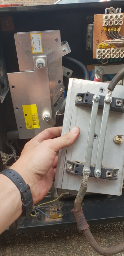
First thing to check is that the contactor (Mike shows this in his picture) is energising. Switch on, pull trigger and check it moves in - The little plastic 'tit' you see between terminals marked 1 and 43 should move inwards. If it doesn't you have a failed coil and need to replace the complete unit. This is a very common failure on these machines with that type of contactor. New one is fairly easy to find and not hard to wire up.
Dave
Dave
NotANormalCoder
Retired fixer of welders
- Messages
- 315
- Location
- Surbiton - Surrey -UK
So that's fairly good news but it could quite easily be that the contacts within the contactor have failed. Quite common again on the old machines. To check, disconnect from the mains - IMPORTANT -
Next, measure for continuity (ohms) across each of the two main contacts. Contact run vertically top to bottom in your picture and are the terminals nearest the panel it's screwed to. One meter probe to lower screw below upper terminal marked 23 and the other opposite, below the green resistor (remove the resistor for access). Then press 'tit' and measured resistance should be less that 10 Ohms. Do the same for the other pair of main contacts and again you should get below 10 Ohms. If you see an open circuit or high resistance when you press the tit, then that contact has failed. If this is the case, there should be some spare contacts either side of the ones the main wires are connected to, so test each of these as above and if they are good, swap each wire over so these contacts do the switching.
If everything measures good, the about the only things left, are a faulty voltage selector switch, loose/burned out connections to the rectifier, no connection to either the earth socket or torch connector or a damaged torch power cable.
I've just reviewed your pictures and note that you have the very old style rectifier that uses encapsulated diode pairs (the black things with 3 terminals on). The do fail but not so that you get no output, it's more usual to get a rubbish weld condition. Try following the 2 heavy leads from the main (welding) transformer. Set your meter for AC volts, fire up the machine and (carefully) measure across these 2 leads. You should get something like 15-30 volts (from memory) and dependant on what setting the voltage swicth is set for. If you get nothing, either the main transformer has died, the contactor is not doing its job, or there is something wrong with the voltage switch.
Try some/all of the above and report back. It's tough for me trying to diagnose this type of fault by messaging, so feedback/voltages etc really help.
Dave
Luckily enough one of my father in laws friends are welding technicians, he just give it a once over and thinks its the rectifier as its the model where they changed it for price reasons?, he thinks around 120 to fix the part does that sound right or is it worth buying the part online and giving it a go myself
NotANormalCoder
Retired fixer of welders
- Messages
- 315
- Location
- Surbiton - Surrey -UK
The type of rectifier you have, was a very early version and the diode packs I mentioned above, do fail after many years. Unfortunately they are no longer made, so you will need to replace the complete assembly with a 'plate' style rectifier bridge if you are sure that this rectifier has failed. Please do the test I suggested - measure for AC volts going into the rectifier from the main transformer. If you do see volts going in and you are sure that no DC volts are going out from the rectifier, you can be sure it's dead. A decent welding engineer should be capable of measuring the diodes to see if they are faulty. As I said, it would be very unusual for them both to fail completely. Every time I have had this problem, either the machine makes a loud humming noise when the trigger is pressed (indicates shorted diodes) or the welding output is very rough/unuseable (open circuit diodes).
Fitting a plate type rectifier is fairly easy but you will need to remove the old unit and its aluminium heatsink, mark the wires - AC Input (from the main transformer), Positive output (to torch) and negative output (to earth lead). Get a rectifier which is single phase, 4 plate, full wave bridge type, for MIG welding (not plasma!!) with a minimum180 Amp capacity and check your the measurements so you have enough room. You will also need to rearrange the various connection arms on the new rectifier (very carefully) so that you can connect the supply and output cables. I reckon that this takes me about 1.5 hours to do, but I have done a good few of these.
Technical Arc (01904 410041) supply a 230A part for around £45 plus carriage and VAT, which is what I would use. They do a cheaper 1 bolt fixing type which is around £10.00 cheaper but has a lower capacity.
If you go down this route, I am happy to provide further advice, but PM me to save space on the forum.
Dave

Was a faulty rectifier as the diodes had packed up, Excellent information from dave! A 230amp bridge style recrifier was replaced and now im up and running again,
Can anyone answers these two questions?
How do you safely run a welder off an extension cable? I havent done so yet but id imagine i need a purpose cable?
Im based in thurrock how can i get my welding career off to a start?
Can anyone answers these two questions?
How do you safely run a welder off an extension cable? I havent done so yet but id imagine i need a purpose cable?
Im based in thurrock how can i get my welding career off to a start?
