


Hello, I'm new to the forum; I have read many posts with interest over the years and I am now looking for help following my bumpy start to tig welding.
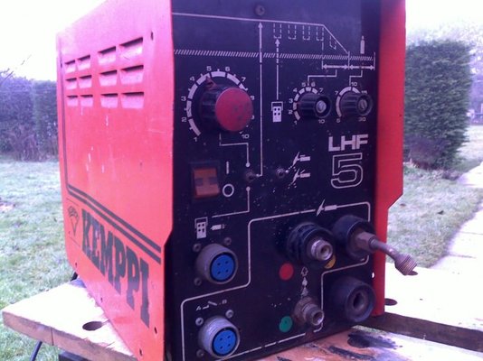
I bought a Kemppi LHF5 from a disposal sale, history unknown.
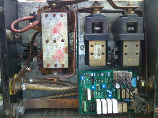
This is an add-on HF unit so to try it out I made up a pair cables with male/female dinze connectors to my small dc inverter welder. I produced an arc and ran a short bead but stopped when the smell of burning alerted me to smoke coming out of the HF machine louvres, photos attaced.
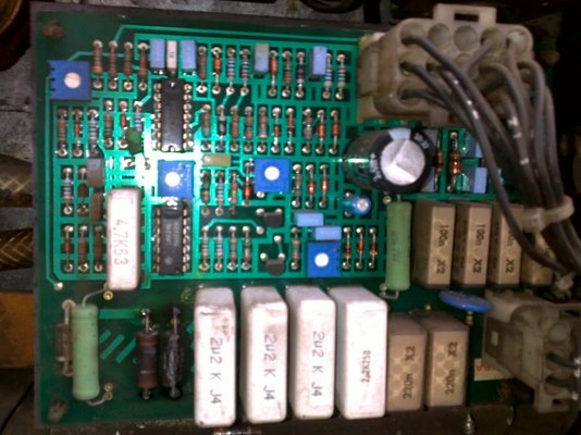
I disconnected the unit from the mains and removed the cover; two components on the small pcb were burnt and still hot (small pcb is on right hand side when looking from the front panel, two components look to me like resistors, ~5mm dia x 10mm long, attached pic3.jpg, just to left of the 4 white blocks at bottom of photo).
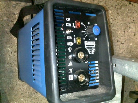
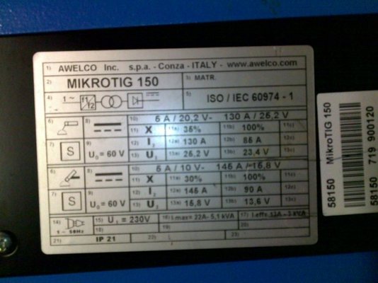
I connected +'ve to +'ve and -'ve to -'ve between dc welder and HF unit. Both welder and HF unit use a 240vac mains supply. The dc inverter is a small Italian Mikrotig 130 amp machine; the controls include an MMA/TIG selector. The tig operation I assumed was 'scratch start' so the HF add-on unit would be an idea addition; I selected 'TIG' for the trial run. Upon further investigation, I've read the manual; the 'TIG' setting is for 'lift arc' mode and provides a lower voltage than the 'MMA' setting (13.6V Vs 23.4V), pic5.jpg attached.
Have I made a big and incorrect assumption that any dc welder is suitable for current supply to this HF unit?
Do I need a different type of welding power source for use with this type of unit?
What is the function of the small RH pcb?
Is it likely to be economical to repair this unit?
Where is the best place to get it repaired, local Norwich area or send via courier is a particular repair shop?
I appreciate any help and advice.
Best regards, Tim
I bought a Kemppi LHF5 from a disposal sale, history unknown.
This is an add-on HF unit so to try it out I made up a pair cables with male/female dinze connectors to my small dc inverter welder. I produced an arc and ran a short bead but stopped when the smell of burning alerted me to smoke coming out of the HF machine louvres, photos attaced.
I disconnected the unit from the mains and removed the cover; two components on the small pcb were burnt and still hot (small pcb is on right hand side when looking from the front panel, two components look to me like resistors, ~5mm dia x 10mm long, attached pic3.jpg, just to left of the 4 white blocks at bottom of photo).
I connected +'ve to +'ve and -'ve to -'ve between dc welder and HF unit. Both welder and HF unit use a 240vac mains supply. The dc inverter is a small Italian Mikrotig 130 amp machine; the controls include an MMA/TIG selector. The tig operation I assumed was 'scratch start' so the HF add-on unit would be an idea addition; I selected 'TIG' for the trial run. Upon further investigation, I've read the manual; the 'TIG' setting is for 'lift arc' mode and provides a lower voltage than the 'MMA' setting (13.6V Vs 23.4V), pic5.jpg attached.
Have I made a big and incorrect assumption that any dc welder is suitable for current supply to this HF unit?
Do I need a different type of welding power source for use with this type of unit?
What is the function of the small RH pcb?
Is it likely to be economical to repair this unit?
Where is the best place to get it repaired, local Norwich area or send via courier is a particular repair shop?
I appreciate any help and advice.
Best regards, Tim
Last edited:
