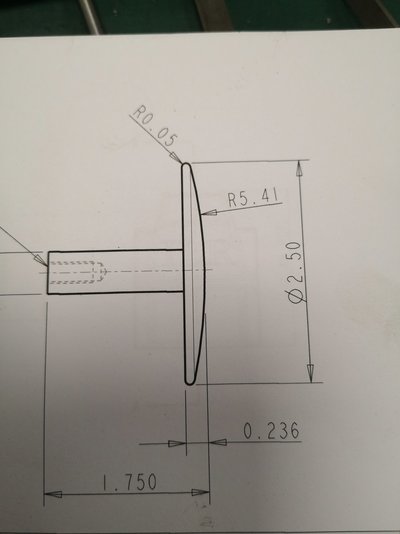
Looking for a bit of assistance, got a few of these to make (out of 304 stainless) Currently I have enough material for 1, so mondays task will be to source some more. Anyway, I have never done this before and wondered if someone could assist with guidance on programing the DRO. The little ball turning attachment won't assist me on this occasion
Do you have a link to the DRO manual? All the classic texts on this idea machine it as a series of steps and then blend with a file. See attached. Another option is to cut out the radius on a piece of sheet, fix to the bed and spring load a pointer directly under the tool tip on the carriage to it. See also page 67 here: https://archive.org/download/treatiseonplaner00cinc/treatiseonplaner00cinc.pdf (turn page on its side so it looks more lathe-like)
You don't need a DRO to do those, there's a simple method which I read recently and was impressed by it's simplicity. All you need is a piece of rod, pointed both ends, which is the same length as your radius of 5.41". Put a centre-punch mark directly under the spindle centre-line, and another on the cross slide directly under the tool. Now all you have to do is hold the carriage against the rod with the handwheel and use the cross-slide to face the part. The rod will cause the tool to follow the radius you require. Here's an example of someone turning a model loco buffer (His distance rod is not horizontal, but if the radius is critical it must be)
Just seen this, which is same principle and rather clever (allows use of power cross feed for good finish). With the addition of a spring, the one Pete. shows would also allow power feed. If you really want a DRO method and have appropriate facial hair, try this: No lathe? Try attached method (stolen from https://www.practicalmachinist.com/...dius-surface-no-cnc-radius-attachment-314091/)
Good examples Actually, thinking about it there is no requirement for the pointed rod to be on the spindle line. All that's required is that 1. It's horizontal and 2. It's in line with the bedway when the tool is right on the centre.
Good point. Thus, I think you could substitute tailstock for headstock and cut concave*. Also, if the headstock to part face distance is bigger than radius required, your movable bedstop could be the pivot. We have to think about if you need, say, a 20" radius on a part only 5" from headstock. Bar could be inclined but its length would need to increase in the same way as the infeed changes when screwcutting with an angled compound**. *No spring needed as reaction from tool pressure keeps rod engaged. ** L' = L /cos(angle of inclination)
An old book, but showing different techniques :- https://ia800208.us.archive.org/35/items/machiningtapered00dowdrich/machiningtapered00dowdrich.pdf Also worth checking out other books available on there :- https://archive.org/search.php?query=publisher:"The+Industrial+Press"&sort=-downloads&page=1