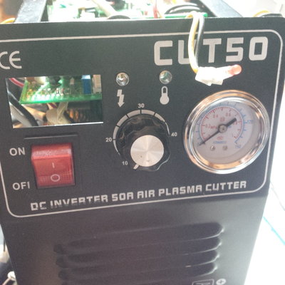
I've been given a CUT50 in bits, as the last stage before the bin, which I'm wading through to see what doesn't work. I've managed to put the boards back together and have traced the majority of the block diagram. I haven't got a compressor to test it with, so I'm limited to basic electrical functions.
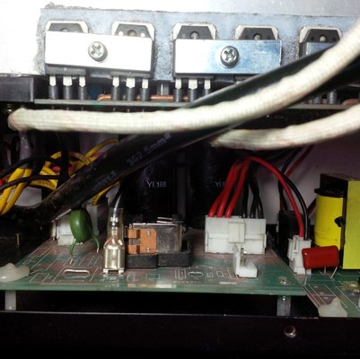
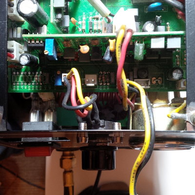
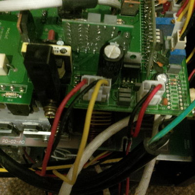
The mains has a thermistor across it, and a relay with a 24V coil which I suppose should kick in under load. I can't find a 24V switched supply anywhere, nor where this relay is supposed to be switched from.
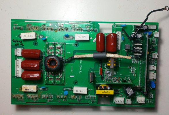
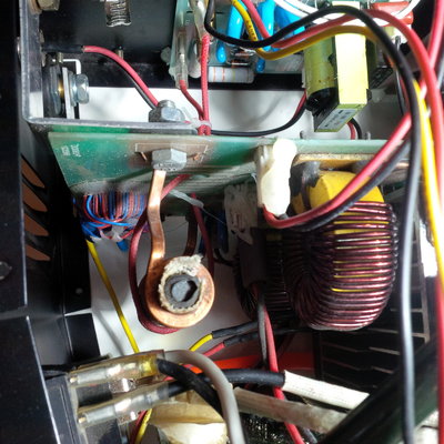
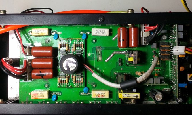
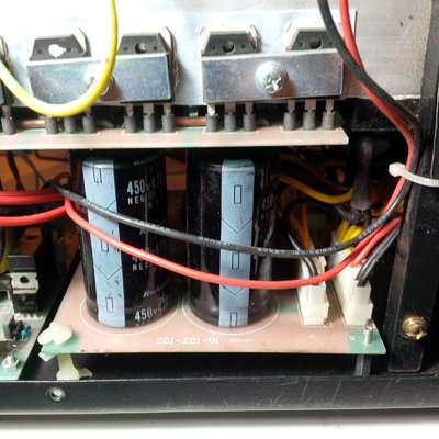
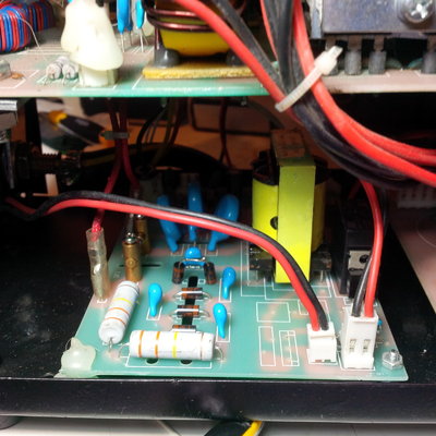
If I turn the box on, I get a continuous arc from the HF contacts on the HF board. This fades as the thermistor heats up. There's a good 330V from the rectifier board, though they've saved some dosh with only having three filter capacitors rather than the four labelled on the board!
I'll post some pictures once I get the board out again, as I believe these are all pretty much the same so no doubt someone has some idea of the connections. I've gone through all the threads I can find on here but can't find just the right views!
The mains has a thermistor across it, and a relay with a 24V coil which I suppose should kick in under load. I can't find a 24V switched supply anywhere, nor where this relay is supposed to be switched from.
If I turn the box on, I get a continuous arc from the HF contacts on the HF board. This fades as the thermistor heats up. There's a good 330V from the rectifier board, though they've saved some dosh with only having three filter capacitors rather than the four labelled on the board!
I'll post some pictures once I get the board out again, as I believe these are all pretty much the same so no doubt someone has some idea of the connections. I've gone through all the threads I can find on here but can't find just the right views!