Hi all,
Just wondering if there are any experts that can verify how a 'general' intermittent weld should be shown on a drawing?
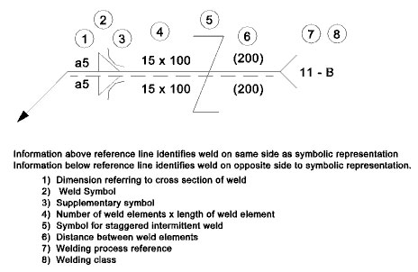
ISO 2553 says to specify the number of weld elements (15 in the picture below) x length of weld element (100 in the picture below). But I need to make a generic design where the number of elements can vary. Really, I just want to specify the weld element length and distance between weld elements, for example 50mm weld length with 150mm distance between weld elements. Would you show this as "50 (150)", or "n x 50 (150)" with a note to say that n is variable? Or is there some other way of doing this?
Thanks in advance
Just wondering if there are any experts that can verify how a 'general' intermittent weld should be shown on a drawing?
ISO 2553 says to specify the number of weld elements (15 in the picture below) x length of weld element (100 in the picture below). But I need to make a generic design where the number of elements can vary. Really, I just want to specify the weld element length and distance between weld elements, for example 50mm weld length with 150mm distance between weld elements. Would you show this as "50 (150)", or "n x 50 (150)" with a note to say that n is variable? Or is there some other way of doing this?
Thanks in advance