You are using an out of date browser. It may not display this or other websites correctly.
You should upgrade or use an alternative browser.
You should upgrade or use an alternative browser.
Lister LT1 Markon genny under voltage!
- Thread starter Welderherup
- Start date
Welderherup
Member
- Messages
- 62
- Location
- Lisburn
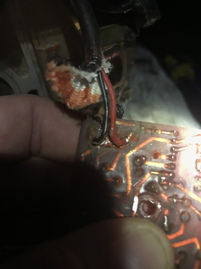
Thanks for help. There are 3 wires going to my old damaged board. Two spades and one soldered. There is a board under the transformer with multiple wires going to it. It’s got x, xx, x, xx. Maybe I need to take one of those from the bottom board and put it on the new board?
Ubique
Member
- Messages
- 2,303
- Location
- East Midlands
As per post 21, it is vital that x and xx are connected the correct way round.
Lister LT1 Markon genny under voltage!
Hello all. I found the forum from doing google searches. I’ve a workshop in Lisburn. I’m an amateur engineer. Welders, oxy, lathe. Play with racing bikes mostly. So I’ve wanted a diesel genny incase of Armageddon etc and got a wee single lister. She was working fine and then one day the voltage...
www.mig-welding.co.uk
Welderherup
Member
- Messages
- 62
- Location
- Lisburn
It appeared only 3 wires were going to the board but what I thought was one turned out to be 2. So I can figure out x and xx easy enough but these red and black wires.....The wiring diagram shows they go to 7 and 8 on the new board. There is a fuse on the diagram, should I add one? Does that fuse in the diagram suggest that’s where the red wire goes?


Welderherup
Member
- Messages
- 62
- Location
- Lisburn
I’m about to connect this up and I’m not sure. So x and xx come directly from the rings. They are the red and black wires. The other two wires are L1 and L2. Initially I thought L1 and L2 were the x and xx wires but when I cut the red and black off the old board I realised that those go directly to the rings and are labelled x and xx near the rings. So L1 and L2 go to position 7&8 on the new board. It’s a 50/50 I get it right but I’m not sure if these are as important to be correct as x and xx
any one know where L1 and L2 goes?
any one know where L1 and L2 goes?
Welderherup
Member
- Messages
- 62
- Location
- Lisburn
Thanks. Will do, I’ve just to figure out if it goes on f1 or F2. Do you know where f1 and F2 go? It’s between 7&8 on the new board.Yup, I'd stick a low value fuse in line with the phase conductor.
Ubique
Member
- Messages
- 2,303
- Location
- East Midlands
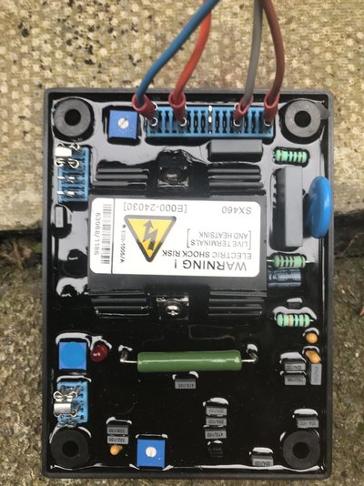
X & XX are polarity sensitive and definitely need to be correctly connected, 7 & 8 are the sensing wires, as it's essentially a 'floating' AC voltage, the polarity is not important, all terminals 7 & 8 need to see is the potential difference between the output wires to control the level of excitation on X & XX. The fuse is there just to break the circuit (and power down the excitation output) in the event of a fault. It can be on the (nominally) 'neutral' side but it's good practice to put it on the 'phase' wire - none of which matters until a ground connection is introduced.
Welderherup
Member
- Messages
- 62
- Location
- Lisburn
Ok thanks for explaining it for me. Hope this fixes it!X & XX are polarity sensitive and definitely need to be correctly connected, 7 & 8 are the sensing wires, as it's essentially a 'floating' AC voltage, the polarity is not important, all terminals 7 & 8 need to see is the potential difference between the output wires to control the level of excitation on X & XX. The fuse is there just to break the circuit (and power down the excitation output) in the event of a fault. It can be on the (nominally) 'neutral' side but it's good practice to put it on the 'phase' wire - none of which matters until a ground connection is introduced.
Ubique
Member
- Messages
- 2,303
- Location
- East Midlands
Don't forget you'll need to trim the voltage in once the engine is running nice & stable - it's the multiturn potentiometer next to the 'XX' terminal - you should have a nice blue 'trim pot' adjuster that came with the AVR, Engine speed should be 1500 3000rpm for 50Hz on a single phase generator
Last edited:
Welderherup
Member
- Messages
- 62
- Location
- Lisburn
Yes I will thanks. I bought a meter that gives me frequency so I will give it a run tomorrow and tune it all in. Will report back hopefully with good news. I had just about given up with this and tired 3 different forums until I found the thread with the above video. Cant run it tonight as it makes enough noise to shake the window panes next door lol
Welderherup
Member
- Messages
- 62
- Location
- Lisburn
So gave it a run this morning. Started the genny on low throttle. When it fired up the voltage was over 300 and the LED light was on the new board indicating low frequency. I tried the adjuster on the board and there was no effect on the voltage at all. I turned up the rpm to bring the frequency up to see if I could put the voltage down then. Brought it up until the led went off and the voltage was now 315. Tried the adjuster on the board. No effect at all. Tried the other adjuster at the bottom of the new board at different locations relative to the top one. No effect. The meter I bought for reading frequency doesn’t work or the frequency is outside 47-63 range of the meter.
anyone have any idea as to what is happening? to recap it was making too much voltage before the new board but the voltage fell away until it was only making 50v whereas now it’s making a steady 300+
I can turn the rpm down as low as possible to get 250v but the led is on showing low frequency. Pity the meter I bought isn’t working. I didn’t get any reading at all through the whole rpm range so I suspect the meter is kaput. If it’s turning off the led it must be within the 47-63 range of the meter
Ubique
Member
- Messages
- 2,303
- Location
- East Midlands
Have you got the jumper links on the board in the correct place for your configuration?
The lower adjuster is for stability, you won't see any change without a load being connected / disconnected. There should be some change in voltage when you turn the top potentiometer.
Are you getting the same measured voltage at terminals 7 & 8 on the AVR?
The lower adjuster is for stability, you won't see any change without a load being connected / disconnected. There should be some change in voltage when you turn the top potentiometer.
Are you getting the same measured voltage at terminals 7 & 8 on the AVR?
Welderherup
Member
- Messages
- 62
- Location
- Lisburn
Welderherup
Member
- Messages
- 62
- Location
- Lisburn
L1 and L2 is 7 and 8
80v (DC??) across X & XX???Across x-xx I’m getting 80
Across L1-L2 I’m getting 130 which is about half of the output voltage at this rpm. I think the link is in the correct place. I didn’t move it. I’m not running anything external apart from this new board
View attachment 319362
Note it has to be DC.
That offload ought to be more like 12vdc to give 240v.
Welderherup
Member
- Messages
- 62
- Location
- Lisburn
Ah wait I didn’t change the setting on the meter. I will go and check it on the correct setting
Welderherup
Member
- Messages
- 62
- Location
- Lisburn
55 dc across x-xx
Welderherup
Member
- Messages
- 62
- Location
- Lisburn
The voltage adjuster does seem to work very slightly. Maybe - range of 5v of adjustment at most


