You are using an out of date browser. It may not display this or other websites correctly.
You should upgrade or use an alternative browser.
You should upgrade or use an alternative browser.
sip turbo 150 migmate stuck on
- Thread starter bri
- Start date
Hi,
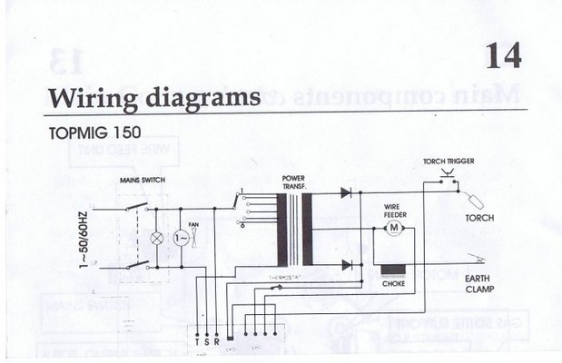
R Kraft is right, the small PCB mounted transformer supplies the Zettler relay which switches on the welding current.
The wire feed motor derives its supply from the rectified output of the main welding transformer hence the voltage changes when different power settings are selected. The wire speed control gives finer adjustment, presumably in conjunction with the High Power Transistor (TIP35C) mounted on the PCB.
The supply to Zettler relay is interupted by the opening of a 'overheat' thermostat in the main transformer in the event the transformer duty cycle is exceeded (ie it gets too hot). The relay is also controlled by the trigger in the torch handle.
There are very few components on the board so replacing them should be easy if you are handy with a soldering iron.
I doubt you have damaged the main welding transformer or its associated rectifier pack. The worst you could have done was to apply live main to both sides of the primary winding at the same time in which case no current would flow in it or the secondary. In any case no significant current flows through the rectifier pack unless you are actually welding and they'll withstand many hundreds of 'reverse' volts.
Your fuse blew probably as a result of something on the PCB giving up (as you suspect). Reversing R & T would cause a short across the incoming mains and blow the fuses as can be seen from the circuit diagram I posted.For the few quid involved replace the lot and all should then be OK (I must contact RS about a commission at this rate ).
).
Take extra special care and at the very least if you are going to apply power with the cover off do keep one hand in your pocket and apply it through a 10mA trip current RCCD (the sort that protects garden power tools) since in the event of further mishap it will at least kill the supply quickly. This is no guarantee to prevent a shock but its a long sight better than a 13 Amp fuse!
Peter
R Kraft is right, the small PCB mounted transformer supplies the Zettler relay which switches on the welding current.
The wire feed motor derives its supply from the rectified output of the main welding transformer hence the voltage changes when different power settings are selected. The wire speed control gives finer adjustment, presumably in conjunction with the High Power Transistor (TIP35C) mounted on the PCB.
The supply to Zettler relay is interupted by the opening of a 'overheat' thermostat in the main transformer in the event the transformer duty cycle is exceeded (ie it gets too hot). The relay is also controlled by the trigger in the torch handle.
There are very few components on the board so replacing them should be easy if you are handy with a soldering iron.
I doubt you have damaged the main welding transformer or its associated rectifier pack. The worst you could have done was to apply live main to both sides of the primary winding at the same time in which case no current would flow in it or the secondary. In any case no significant current flows through the rectifier pack unless you are actually welding and they'll withstand many hundreds of 'reverse' volts.
Your fuse blew probably as a result of something on the PCB giving up (as you suspect). Reversing R & T would cause a short across the incoming mains and blow the fuses as can be seen from the circuit diagram I posted.For the few quid involved replace the lot and all should then be OK (I must contact RS about a commission at this rate
).Take extra special care and at the very least if you are going to apply power with the cover off do keep one hand in your pocket and apply it through a 10mA trip current RCCD (the sort that protects garden power tools) since in the event of further mishap it will at least kill the supply quickly. This is no guarantee to prevent a shock but its a long sight better than a 13 Amp fuse!
Peter
Last edited: