I was wondering that it is possible we may have skipped a few stages.
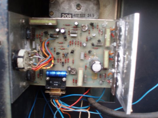
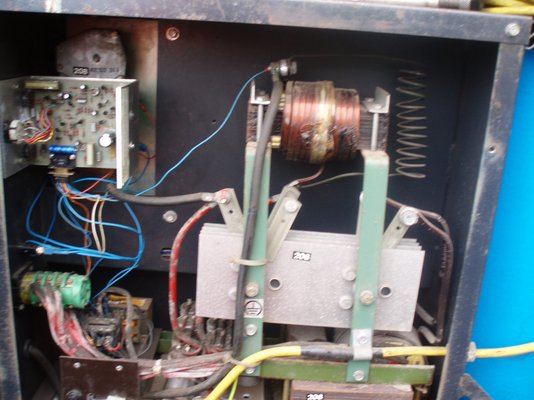
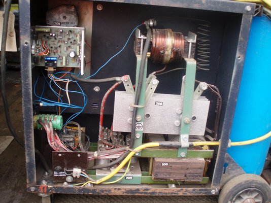
Looking at the circuit the motor does use the welding voltage via a control circuit on the PCB to vary the wire speed, but the PCB it self is still powered from the small transformer down there at the bottom of the welder.
The circuit shows a few things such as a fuse in line or a breaker?, not really clear on the main circuit. But could I suggest a check for volts on the Red circled diode on the control board. It should have 24 Volts across it and if there is then it would quickly show the small transformer/fuse etc is all OK.
The control board does seem to be the same as Snooper posted and is also the same as the circuit I posted earlier.
So here we are:
View attachment 82143
View attachment 82145
The small transformer provides AC to the board. Half wave rectified by D1 (bottom right) R10 is a 680 OHm resister provides current to the diode Z1 Zener diode at 24 Volts and smoothed by C9 a 10 uF capacitor.
Just checked voltage on diode and if ive done it right it measures 52 volts!! i dont know if this is relevent but it will not trigger at all on the first two settings of the three position switch. it only works when its turned to the broken line position. i thought that was for when you are spot welding? it allways worked on the first position before i.e. continuous weld.
The bottom half of the circuit seems to be the control for continuous welding spot and stitch welding, so if these are not working correctly could point to an issue on this side of the PCB. It looks as though T7 the BC237 has to switch on to allow the motor speed control to work.
If no 24 Volts across the diode, could you check for approx 27 volts AC across 2-6 and 5-9 of the connector.
Again just my thoughts
Adrian


You are using an out of date browser. It may not display this or other websites correctly.
You should upgrade or use an alternative browser.
You should upgrade or use an alternative browser.
Back Again same fault
- Thread starter stanman
- Start date
Just checked voltage on diode and if ive done it right it measures 52 volts!! i dont know if this is relevent but it will not trigger at all on the first two settings of the three position switch. it only works when its turned to the broken line position. i thought that was for when you are spot welding? it allways worked on the first position before i.e. continuous weld.
Well 52 volts is not correct as the highest Zener diode voltage is 27 Volts and that is for Z5. Z1 is a 24 volt Zener so that is the max I would expect to see on that.
Barring a reading error, I could only suggest that you seek some local expert help as it is difficult to remote diagnose or provide more then basic guessing assistance. At least you have the above circuits and layouts, they are not the best layouts but will help.
Hope it goes well and you can get it working soon.
Adrian
p.s. if it has been looked at before and any components changed then the circuit would allow them to check they have used the correct parts, it is possible that Z1 is no longer a zener It looks like a nice clean component?
thanks Adrian, ive sent the drawings off to my friend so he can now make sure the parts he changed are correct. if it turns out to be a pcb fault still, i might send it up to scotland to the people who repaired it before when i had a fault on it. the only problem is the bill is rising and i must decde when to call it aday with the old girl!!! it is 37 years old now and it has done a lot of work over the years. thanks for the help , i'll let you know what happens, regards, stanman
the snooper
getting older by the day
- Messages
- 21,065
- Location
- Hull UK
if you can solder, you could just replace most parts cheaply the bc237 transistors (equivalent) are 1.89 for 5
1n4003 diodes 99p for 10 resistors will be cheap as will capacitors
1n4003 diodes 99p for 10 resistors will be cheap as will capacitors
I know the parts are cheap but it's the soldering! I'm terrible at it ! I can weld ok but I tend to muck things up when I try to do it (soldering)!if you can solder, you could just replace most parts cheaply the bc237 transistors (equivalent) are 1.89 for 5
1n4003 diodes 99p for 10 resistors will be cheap as will capacitors
the snooper
getting older by the day
- Messages
- 21,065
- Location
- Hull UK
shame it would have been quite a cheap rebuild, soldering is easy really use a decent hot iron apply heat to the thickest part and as soon as solder flows onto the joint remove heat, heat sensitive components like transistors benefit from a heatsink so as not to destroy them tweezers will doI know the parts are cheap but it's the soldering! I'm terrible at it ! I can weld ok but I tend to muck things up when I try to do it (soldering)!
In a hotel down in Ely back up North Wednesday. Stan, To me it would not make sense to just send off the board unless they have a welder to try it in. Soldering is not a problem, if you can weld you can solder, it is easier.
If you get stuck, send it up to me and I will have a go, it has been my job in electronics for the past 25 plus years, but I would prefer to have the rest to test as a whole. If you have had the welder for 37 years it has done well. Let you friend see what he can do/check with it and let us know some time.
Adrian

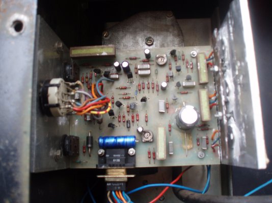
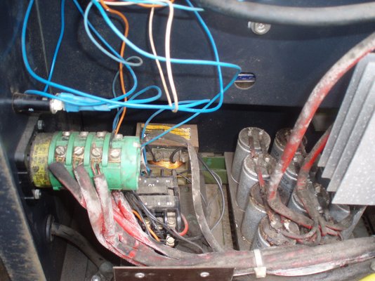
Stanman I've took some pics of mine today it was the earliest I could get to it hope they help. quality doesn't seem to good but.
Rig Pig
Member
- Messages
- 3,744
- Location
- Narrwich! U.K.
Sorry if I sound like the voice of doom but your caps look as knackered as the set I pulled out of my Automig.Stanman I've took some pics of mine today it was the earliest I could get to it hope they help. quality doesn't seem to good but.
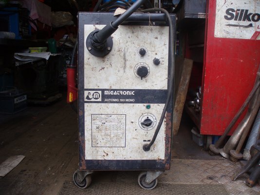
looks very similar but definitely not the same. the pcb looks a different layout. they must have modified them internally just slightly. i think i bought mine in 1979 when i was doing car repairs. i bought it after trying out a really enormous mig ,which i borrowed from someone. i couldn't believe how fast you could weld with them! a vast improvement on the gas welding i was used to.Stanman I've took some pics of mine today it was the earliest I could get to it hope they help. quality doesn't seem to good but.
Any luck with yours?(I bought mine for the same reason and roughly the same time)looks very similar but definitely not the same. the pcb looks a different layout. they must have modified them internally just slightly. i think i bought mine in 1979 when i was doing car repairs. i bought it after trying out a really enormous mig ,which i borrowed from someone. i couldn't believe how fast you could weld with them! a vast improvement on the gas welding i was used to.
Mechman.
Just wondering?
I do not suppose you have a digital meter that you could take a few voltage readings off your PCB so I can compare things.
They are the same PCB, but yours has had replacement caps fitted to it already. The main difference seems to be the trimmer style variable resister P4 has been replaced by the larger potentiometer on the back of the control panel.
Let me know if you can take some measurements and I will suggest a few points to measure between.
Cheers
Adrian
sorry Adrian I'm hopeless with PCBs etc I've had the machine from new and as far as I know the caps have never been touched if they have been they've been very kindly done as freebee.Mechman.
Just wondering?
I do not suppose you have a digital meter that you could take a few voltage readings off your PCB so I can compare things.
They are the same PCB, but yours has had replacement caps fitted to it already. The main difference seems to be the trimmer style variable resister P4 has been replaced by the larger potentiometer on the back of the control panel.
Let me know if you can take some measurements and I will suggest a few points to measure between.
Cheers
Adrian

Thanks for the offer Rig Pig. I will check you pictures later.
I have the board from Stan and at the moment trying to set out a test rig, wiring up a 24 Volt AC supply for the board and, a couple of 24 volt lamps to simulate the gas valve, contactor and wire-feed motor.
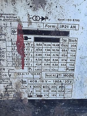
I think from the main circuit I can figure most of it out, What I would like to know is the voltage range of the DC welding volts, but I can make a guess that the unit goes from approx 18 to 30 ish volts on the output from the lowest to highest current settings. So I will probably settle for 24 Volts DC as a mid range point initially.
I will post pictures of the mock up if it gets anywhere.
Adrian
I have the board from Stan and at the moment trying to set out a test rig, wiring up a 24 Volt AC supply for the board and, a couple of 24 volt lamps to simulate the gas valve, contactor and wire-feed motor.
I think from the main circuit I can figure most of it out, What I would like to know is the voltage range of the DC welding volts, but I can make a guess that the unit goes from approx 18 to 30 ish volts on the output from the lowest to highest current settings. So I will probably settle for 24 Volts DC as a mid range point initially.
I will post pictures of the mock up if it gets anywhere.
Adrian
Rig Pig
Member
- Messages
- 3,744
- Location
- Narrwich! U.K.
Thanks for the offer Rig Pig. I will check you pictures later.
I have the board from Stan and at the moment trying to set out a test rig, wiring up a 24 Volt AC supply for the board and, a couple of 24 volt lamps to simulate the gas valve, contactor and wire-feed motor.
I think from the main circuit I can figure most of it out, What I would like to know is the voltage range of the DC welding volts, but I can make a guess that the unit goes from approx 18 to 30 ish volts on the output from the lowest to highest current settings. So I will probably settle for 24 Volts DC as a mid range point initially.
I will post pictures of the mock up if it gets anywhere.
Adrian