fridgefreezer
Member
- Messages
- 31
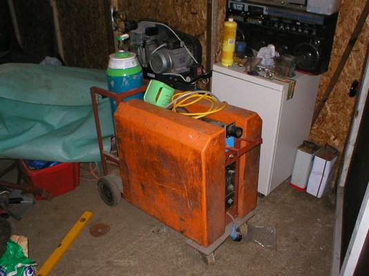
I have an NBC (Butters) AutoWeld2 which is God knows how old (or it may be older than God, I'm not sure).
Anyway, the control transformer (wot makes things click) has burned out - the main transformers are still fine. I reckon it should be easy enough to pop a new universal transformer in there to bring it back to life but I have no idea what voltage I would need.
If anyone can help (a service manual would be perfect, I'd happily pay for someone to copy one for me) it would be much appreciated.
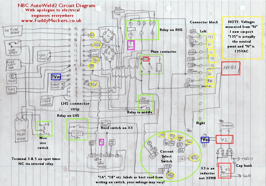
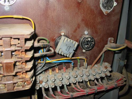
Failing that, a poke about in a working unit with a multimeter or just some general advice on faulting welders would be groovy - anything to save me having to reverse-engineer the circuit and trace all the dusty old wiring through the unit really!
Anyway, the control transformer (wot makes things click) has burned out - the main transformers are still fine. I reckon it should be easy enough to pop a new universal transformer in there to bring it back to life but I have no idea what voltage I would need.
If anyone can help (a service manual would be perfect, I'd happily pay for someone to copy one for me) it would be much appreciated.
Failing that, a poke about in a working unit with a multimeter or just some general advice on faulting welders would be groovy - anything to save me having to reverse-engineer the circuit and trace all the dusty old wiring through the unit really!

 :
:
") A bit pricey at £125 but if you average it out over the 35 years the old one lasted it's not bad value
A bit pricey at £125 but if you average it out over the 35 years the old one lasted it's not bad value  and cheaper than buying a new welder.