


After reading all the threads about upgrading the SIP wire-feed power supply, I finally got round to modifying mine. I took a slightly different approach from the previous threads.
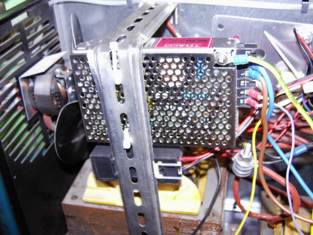
I didn't have a 24V transformer to hand that was meaty enough to drive the motor (we're talking about an amp, I think, but certainly less than two amps) but I did have an old laptop switching supply, 16VDC at 3.6A, which I thought might just be enough, voltage-wise (more than enough current capability).
Now, as pointed out by AdrianH, a switching PSU is likely to suffer if its mains supply is switched on and off repeatedly. I have seen some industrial switching power supplies disappear in a cloud of smoke under these conditions. Also, its output is likely to ramp down slowly when the mains is disconnected, meaning that the motor will run on unacceptably and give more and more "stick-out" after each run. The SIP is bad enough for this as standard without aggravating the problem.
My solution, given the available parts, was to keep the laptop PSU permanently connected to the mains supply (as long as the welder is switched on) and to switch the DC output instead. This also gave the opportunity to make another improvement. More on that later.
Having looked at various schematics here and elsewhere, I realise that the wiring of the modern SIPs (with the troublesome wire-feed) varies from one model to the next and over time, even for the same model. Therefore I'm not going to attempt to describe a procedure of the form "Cut the blue wire..." (as someone said in another thread) because it might not be applicable to all models and someone might end up frying themselves by putting 240VAC onto the torch output or something. Instead, I'll give circuit diagrams showing the modifications. If you can't follow them, find someone who can to help you transfer them to your own welder and do the modification safely.
Oh, and I didn't fit a separate fuse for the power supply for the following reasons:
1. No other part of the internals of the welder has a separate fuse (where's the fuse for the control board with its piddly little transformer?)
2. The 13A plug fitted to the laptop PSU I used was found to be fitted with a 13A fuse - on what can't have been more than a 5A cable
Whether or not you decide to fit a separate fuse for the PSU is entirely up to your judgement and at your own risk.
Anyway, here you go:
This is the original schematic from the manual for my welder, a SIP 130 turbo.
And the modified schematic (modifications in blue).
Running through the modifications, what I have done is:
I have to say straight away that 16VDC isn't really enough. I had to adjust the preset pot on the board all the way to get the wire to crawl (most of the time) with the speed set to minimum. I have to turn the knob about two-thirds of the way up to get an acceptable speed for welding on low-to-medium power. That's just lack of voltage. I have my eye on an industrial 24V switching supply (at 10A ) to replace it and get the speed up in order to weld at higher power settings.
However, it welds so much more smoothly and controllably than it did before (as you'd expect from previous reports about similar mods). Also, wire run-on is a thing of the past. Experimenting with and without the "braking" wire connected, I can even hear the difference. Without it, the motor audibly spins down after releasing the trigger. With it, the motor just stops dead
I'll replace the supply with a higher-voltage one but I'm pleased to have proven the principle and shown that if you do only have a switching PSU to hand, there is a way to use it in this application.
This would also work, though, if you replaced the switching PSU with a 24V transformer and a bridge rectifier. Additionally, it means that should you wish, you could add a smoothing capacitor to the output of the rectifier without worrying about the motor running on as the capacitor discharged.
I didn't have a 24V transformer to hand that was meaty enough to drive the motor (we're talking about an amp, I think, but certainly less than two amps) but I did have an old laptop switching supply, 16VDC at 3.6A, which I thought might just be enough, voltage-wise (more than enough current capability).
Now, as pointed out by AdrianH, a switching PSU is likely to suffer if its mains supply is switched on and off repeatedly. I have seen some industrial switching power supplies disappear in a cloud of smoke under these conditions. Also, its output is likely to ramp down slowly when the mains is disconnected, meaning that the motor will run on unacceptably and give more and more "stick-out" after each run. The SIP is bad enough for this as standard without aggravating the problem.
My solution, given the available parts, was to keep the laptop PSU permanently connected to the mains supply (as long as the welder is switched on) and to switch the DC output instead. This also gave the opportunity to make another improvement. More on that later.
Having looked at various schematics here and elsewhere, I realise that the wiring of the modern SIPs (with the troublesome wire-feed) varies from one model to the next and over time, even for the same model. Therefore I'm not going to attempt to describe a procedure of the form "Cut the blue wire..." (as someone said in another thread) because it might not be applicable to all models and someone might end up frying themselves by putting 240VAC onto the torch output or something. Instead, I'll give circuit diagrams showing the modifications. If you can't follow them, find someone who can to help you transfer them to your own welder and do the modification safely.
Oh, and I didn't fit a separate fuse for the power supply for the following reasons:
1. No other part of the internals of the welder has a separate fuse (where's the fuse for the control board with its piddly little transformer?)
2. The 13A plug fitted to the laptop PSU I used was found to be fitted with a 13A fuse - on what can't have been more than a 5A cable
Whether or not you decide to fit a separate fuse for the PSU is entirely up to your judgement and at your own risk.
Anyway, here you go:
This is the original schematic from the manual for my welder, a SIP 130 turbo.
And the modified schematic (modifications in blue).
Running through the modifications, what I have done is:
- Connected the AC input for the PSU to the switched mains supply, just after the on-off switch. Not shown is the earth connection. I connected this to the main earth point in the welder case.
- Cut the connection from the welding voltage DC output to the motor controller at CN1 (the wire from CN5 to CN1) and connected the "+" output from the PSU instead.
- Connected the "-" output from the PSU to the negative connection from the welding transformer, which is also the negative terminal of the motor. This and the preceding step effectively replace the welding voltage with the laptop PSU voltage as the motor power supply.
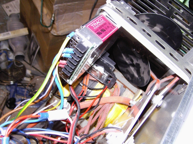
- Now, the switching. I used a relay with a 240V AC coil and connected the coil between live (L1) and the switched neutral from the control board to the primary of the welding transformer. This takes the place of the 24V transformer used on other versions of the wire-feed mod and causes the relay to be energised whenever the torch trigger is pressed (and thereby the welding transformer switched on).
- For the contacts of the relay, I connected the common terminal to the motor positive terminal and moved the output wire of the motor controller from the motor positive terminal to the normally-closed terminal on the relay. In this way, the output of the motor controller is only connected to the motor when the torch trigger is pressed. Clever, eh?
- But there's more! Having a spare normally-closed contact on the relay (a terminal that is now connected to the motor positive when the torch trigger is not pressed), I connected this to the negative side of the motor. So when the torch trigger is released, not only is power removed from the motor, the two terminals of the motor are shorted together. This acts as a very effective brake on the motor and practically eliminates run-on of the wire-feed when the trigger is released.
I have to say straight away that 16VDC isn't really enough. I had to adjust the preset pot on the board all the way to get the wire to crawl (most of the time) with the speed set to minimum. I have to turn the knob about two-thirds of the way up to get an acceptable speed for welding on low-to-medium power. That's just lack of voltage. I have my eye on an industrial 24V switching supply (at 10A
) to replace it and get the speed up in order to weld at higher power settings.However, it welds so much more smoothly and controllably than it did before (as you'd expect from previous reports about similar mods). Also, wire run-on is a thing of the past. Experimenting with and without the "braking" wire connected, I can even hear the difference. Without it, the motor audibly spins down after releasing the trigger. With it, the motor just stops dead
I'll replace the supply with a higher-voltage one but I'm pleased to have proven the principle and shown that if you do only have a switching PSU to hand, there is a way to use it in this application.
This would also work, though, if you replaced the switching PSU with a 24V transformer and a bridge rectifier. Additionally, it means that should you wish, you could add a smoothing capacitor to the output of the rectifier without worrying about the motor running on as the capacitor discharged.


")


